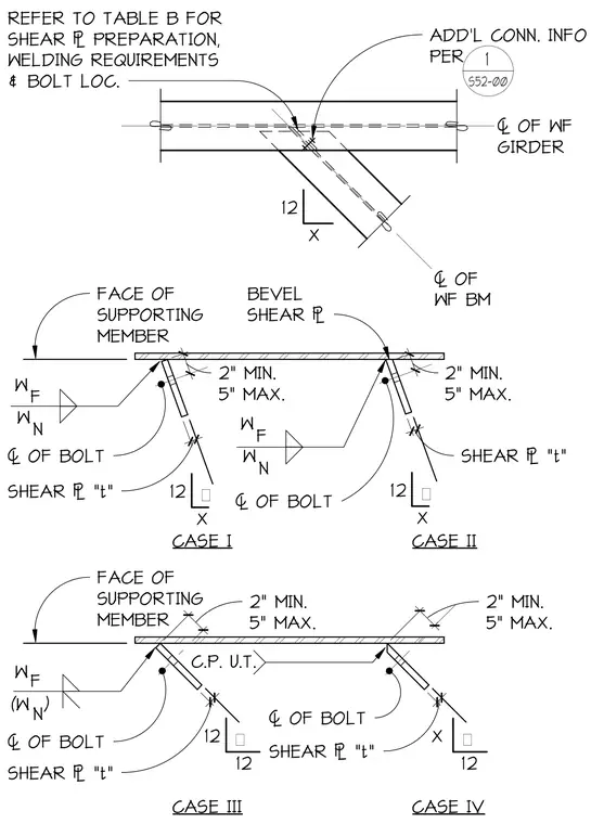
Four standard connection cases illustrate the detailing of shear plates framing wide-flange beams into supporting members. Each case designates the face of the supporting member, centerlines of bolts, and specific weld symbols including fillet welds and complete joint penetration or ultrasonic testing designations where required. Bevel shear plates maintain minimum and maximum dimensioned clearances from the support face. Additional connection information directs the user to Table B for shear plate preparation, welding requirements, and bolt locations.
ADD'L CONN. INFO PER " OF WF GIRDER 12 X " OF WF BM REFER TO TABLE B FOR SHEAR PREPARATION, WELDING REQUIREMENTS & BOLT LOC. W F W N FACE OF SUPPORTING MEMBER BEVEL SHEAR 2 1 / 2" 2" MIN. 5" MAX. 3/4 " SHEAR "t" Θ W F W N 2" 2" MIN. 5" MAX. 3/4 " 12 X SHEAR "t" Θ FACE OF SUPPORTING MEMBER CASE I CASE II W F (W ) N " OF BOLT " OF BOLT " OF BOLT 2 1/ 2" 2" MIN. 5" MAX. 3/4 " SHEAR "t" 12 12 Θ C.P. U.T. 2 1/ 2" 2" MIN. 5" MAX. " OF BOLT 3/4 " SHEAR "t" X 12 Θ CASE III CASE IV 12 X 1 S52-00
Members view this detail in full resolution, download the CAD files (SVG, PDF), and can adapt it in the built-in CAD editor — export DXF, DWG, or PDF.
Start membership