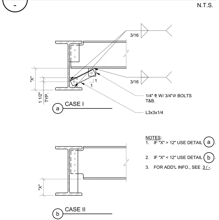
Typical beam bracing conditions are designated as Case I and Case II based on dimension "X". Case I incorporates an L3x3x1/4 structural angle brace connected with 3/4-inch diameter bolts top and bottom to a 1/4-inch connection plate, welded with 3/16-inch fillet welds. Case II provides standard spacing without the added angle brace when dimension "X" varies. Notes direct the installer to select the appropriate detail depending on whether "X" is greater than or less than 12 inches.
CASE I a "X" 1 1/2" 1 1 3/16 3/16 1/4" ⅊ W/ 3/4" ⌀ BOLTS T&B. L3x3x1/4 NOTES: 1. IF "X" > 12" USE DETAIL . 2. IF "X" < 12" USE DETAIL . 3. FOR ADD'L INFO., SEE . a b 3 / - CASE II b "X" TYP. - N.T.S.
Members view this detail in full resolution, download the CAD files (SVG, PDF), and can adapt it in the built-in CAD editor — export DXF, DWG, or PDF.
Start membership