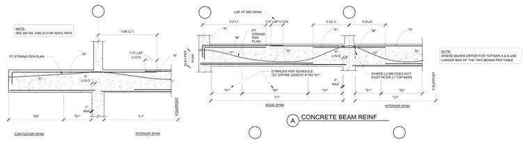
Concrete beam reinforcing requirements span edge spans, interior spans, and cantilever spans. The assembly incorporates top and bottom reinforcing bars designated by letters A through D, along with stirrups sized per schedule placed at specified spacings. Post-tensioning strands run per plan with draped profiles extending into supports. Lap splices of one foot are indicated unless noted otherwise, with specific hook requirements for top bars where intersecting beams do not exist. Additional notes specify using the larger bar size when beams differ at continuous supports.
F/SUPPORT 1'-0" LAP U.O.N. "A" "C" "D" "A" "B" "A" "C" "D" 0.2(L1) 0.2(L2) MAX 2" U.N.O. 6" "L1" "L2" "S1" "S2" "S1" "S1" "S2" EDGE SPAN INTERIOR SPAN STIRRUPS PER SCHEDULE "S2" ENTIRE LENGTH IF NO "S1" WHERE L2 BM DOES NOT EXIST HOOK L1 TOP BARS NOTE: WHERE BEAMS DIFFER FOR TOP BAR A & B USE LARGER BAR OF THE TWO BEAMS PER TABLE LAP AT MID-SPAN A CONCRETE BEAM REINF "B" PLAN ELEV PER 0.2*L1 PT STRAND PER PLAN NOTE: SEE DETAIL 9/S5.20 FOR ADD'L INFO CANTILEVER SPAN INTERIOR SPAN F/SUPPORT 0.66 (L1) U.O.N. 1'-0" LAP U.N.O. 6" MAX 2" "S2" "S1" "A" "A" "C" "L1" PT STRAND PER PLAN
Members view this detail in full resolution, download the CAD files (SVG, PDF), and can adapt it in the built-in CAD editor — export DXF, DWG, or PDF.
Start membership