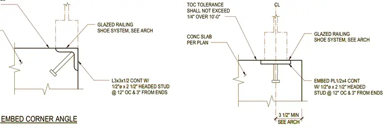
Connection conditions for a glazed railing shoe system anchored to a concrete slab edge and a concrete corner. The slab edge condition utilizes a continuous embed plate measuring one-half inch by four inches, welded with one-half-inch diameter by two-and-a-half-inch headed studs spaced at twelve inches on center with three inches from the ends. The corner condition features a continuous L3x3x1/2 angle embedded in the concrete corner, similarly anchored with one-half-inch diameter by two-and-a-half-inch headed studs at twelve inches on center and three inches from the ends. A minimum concrete cover of three and a half inches is maintained for the embedment. The top of concrete tolerance is specified not to exceed one-quarter inch over ten feet.
CONC SLAB PER PLAN GLAZED RAILING SHOE SYSTEM, SEE ARCH EMBED PL1/2x4 CONT W/ 1/2"ø x 2 1/2" HEADED STUD @ 12" OC & 3" FROM ENDS SEE ARCH 3 1/2" MIN CL GLAZED RAILING SHOE SYSTEM, SEE ARCH CONCRETE EMBED CORNER ANGLE TOC TOLERANCE SHALL NOT EXCEED 1/4" OVER 10'-0" SHALL NOT EXCEED L3x3x1/2 CONT W/ 1/2"ø x 2 1/2" HEADED STUD @ 12" OC & 3" FROM ENDS CONC SLAB PER PLAN GLAZED RAILING SHOE SYSTEM, SEE ARCH EMBED PL1/2x4 CONT W/ 1/2"ø x 2 1/2" HEADED STUD @ 12" OC & 3" FROM ENDS SEE ARCH 3 1/2" MIN CL GLAZED RAILING SHOE SYSTEM, SEE ARCH CONCRETE EMBED CORNER ANGLE TOC TOLERANCE SHALL NOT EXCEED 1/4" OVER 10'-0" SHALL NOT EXCEED L3x3x1/2 CONT W/ 1/2"ø x 2 1/2" HEADED STUD @ 12" OC & 3" FROM ENDS
Members view this detail in full resolution, download the CAD files (SVG, PDF), and can adapt it in the built-in CAD editor — export DXF, DWG, or PDF.
Start membership