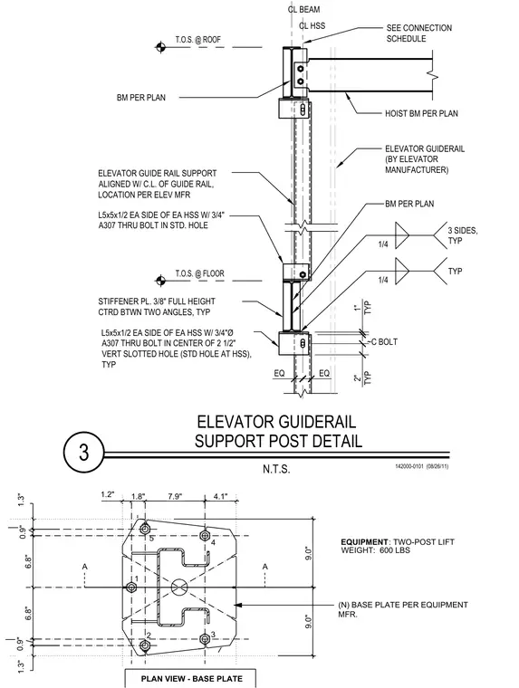
An elevator guiderail support post assembly aligns with the center line of the guide rail and is located per the equipment manufacturer. The hollow structural section beam connects to framing members using L5x5x1/2 angles on each side with three-quarter-inch A307 through-bolts in standard holes. A three-eighths-inch full-height stiffener plate is centered between the two angles, and connections feature quarter-inch fillet welds on three sides. The base plate plan view details a two-post lift configuration weighing six hundred pounds with specified dimensions and anchor hole layouts.
CL BEAM ELEVATOR GUIDE RAIL SUPPORT ALIGNED W/ C.L. OF GUIDE RAIL, LOCATION PER ELEV MFR BM PER PLAN EQ EQ CL HSS BM PER PLAN L5x5x1/2 EA SIDE OF EA HSS W/ 3/4 " A307 THRU BOLT IN STD. HOLE ~C BOLT ELEVATOR GUIDERAIL (BY ELEVATOR MANUFACTURER) 1/4 TYP 3 ELEVATOR GUIDERAIL SUPPORT POST DETAIL N.T.S. 142000-0101 (08/26/11) L5x5x1/2 EA SIDE OF EA HSS W/ 3/4"Ø A307 THRU BOLT IN CENTER OF 2 1/2" VERT SLOTTED HOLE (STD HOLE AT HSS), TYP 2" TYP 1" TYP T.O.S. @ FLOOR T.O.S. @ ROOF STIFFENER PL. 3/8" FULL HEIGHT CTRD BTWN TWO ANGLES, TYP HOIST BM PER PLAN 1/4 3 SIDES, TYP SEE CONNECTION SCHEDULE EQUIPMENT : TWO-POST LIFT WEIGHT: 600 LBS PLAN VIEW - BASE PLATE A A (N) BASE PLATE PER EQUIPMENT MFR. 1.2" 1.8" 7.9" 4.1" 1.3" 0.9" 6.8" 6.8" 0.9" 1.3" 1 2 3 4 5 9.0" 9.0"
Members view this detail in full resolution, download the CAD files (SVG, PDF), and can adapt it in the built-in CAD editor — export DXF, DWG, or PDF.
Start membership