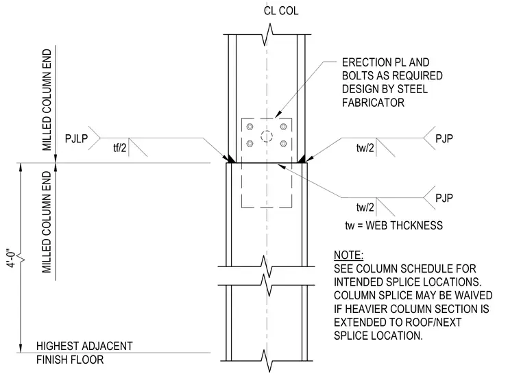
A typical structural steel column splice located four feet above the highest adjacent finish floor features milled column ends bearing directly against one another. The connection utilizes partial-joint-penetration groove welds sized according to the flange and web thicknesses, along with a bolted erection plate designed by the steel fabricator. A general note indicates that splice locations are governed by the column schedule and may be omitted if a heavier column section extends continuously to the next level.
4'-0" ERECTION PL AND BOLTS AS REQUIRED DESIGN BY STEEL FABRICATOR NOTE: SEE COLUMN SCHEDULE FOR INTENDED SPLICE LOCATIONS. COLUMN SPLICE MAY BE WAIVED IF HEAVIER COLUMN SECTION IS EXTENDED TO ROOF/NEXT SPLICE LOCATION. CL COL tw = WEB THCKNESS HIGHEST ADJACENT FINISH FLOOR MILLED COLUMN END MILLED COLUMN END tw/2 PJP tw/2 PJP tf/2 PJLP
Members view this detail in full resolution, download the CAD files (SVG, PDF), and can adapt it in the built-in CAD editor — export DXF, DWG, or PDF.
Start membership