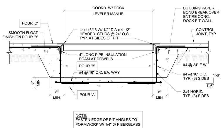
This assembly details a concrete loading dock pit constructed in three distinct pours. The pit edge is reinforced with L4x4x5/16 steel angles anchored by 1/2-inch diameter by 4 1/2-inch long headed studs spaced at 24 inches on center. A building paper bond break is applied over the entire concrete dock pit wall, with control joints provided at typical locations. The concrete slab is reinforced with number 4 rebar at 24 inches on center each way, while the pit walls utilize number 4 rebar at 16 inches on center each way. Four-inch long pipe insulation foam is placed at the dowels to allow for movement. The pit floor and walls are finished with a smooth float finish on pour B, with minimum dimensions of 8 inches for wall thickness and 6 inches for the slab base.
4" LONG PIPE INSULATION FOAM AT DOWELS #4 @ 16" O.C. EA. WAY POUR 'B' SMOOTH FLOAT FINISH ON POUR 'B' #4 @ 24" E.W. BUILDING PAPER BOND BREAK OVER ENTIRE CONC. DOCK PIT WALL CONTROL JOINT, TYP #4 @ 16" O.C. TYP. (3) SIDES 1'-6" 1'-6" 2#4 HORIZ. TYP. (3) SIDES POUR 'A' POUR 'C' MIN. 8" MIN. 6" MIN. 8" LEVELER MANUF. COORD. W/ DOCK L4x4x5/16 W/ 1/2" DIA x 4 1/2" HEADED STUDS @ 24" O.C. TYP. AT SIDES OF PIT NOTE:
Members view this detail in full resolution, download the CAD files (SVG, PDF), and can adapt it in the built-in CAD editor — export DXF, DWG, or PDF.
Start membership