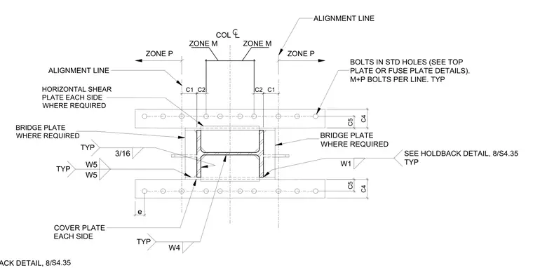
A bolted and welded steel column connection includes cover plates provided on each side. Horizontal shear plates and bridge plates are placed where required to tie the assembly together. Bolts are installed in standard holes with a specified quantity of M plus P bolts per line. Welds include three-sixteenth inch fillet welds along with designated weld sizes W1, W4, and W5 applied typically. Alignment lines and designated zones M and P establish positioning relative to the column centerline.
ALIGNMENT LINE ALIGNMENT LINE ZONE P ZONE P COVER PLATE EACH SIDE COL ZONE M ZONE M W4 TYP 3/16 TYP HORIZONTAL SHEAR PLATE EACH SIDE WHERE REQUIRED W5 TYP W5 C5 C5 BRIDGE PLATE WHERE REQUIRED C4 C4 e C2 C1 C2 C1 W1 SEE HOLDBACK DETAIL, 8/ TYP S4.35 S4.35 SEE HOLDBACK DETAIL, 8/ BOLTS IN STD HOLES (SEE TOP PLATE OR FUSE PLATE DETAILS). M+P BOLTS PER LINE. TYP BRIDGE PLATE WHERE REQUIRED
Members view this detail in full resolution, download the CAD files (SVG, PDF), and can adapt it in the built-in CAD editor — export DXF, DWG, or PDF.
Start membership