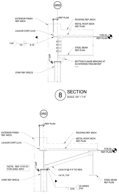
The assembly features a steel beam supporting a metal roof deck with roofing materials referenced to architectural drawings, aligning with a grid line and top of steel elevation marker. A continuous L4x3x3/8 angle is welded to the deck assembly with quarter-inch welds at four to twelve inches typical spacing. Cold-formed metal framing sits below with a one-inch gap maintained from the exterior finish. Bottom flange bracing is provided at each intersecting beam location, utilizing an L3x3x1/4 angle spaced at four feet on center maximum with quarter-inch typical plates welded on three sides. Additional information is referenced on sheet 8-S5-20.
GRID GRID METAL ROOF DECK REF PLAN STEEL BEAM REF PLAN TOS EL REF PLAN EXTERIOR FINISH REF ARCH 1" GAP CFMF REF SPECS BOTTOM FLANGE BRACING AT EA INTERSECTING BM REF ----- REF PLAN ROOFING REF ARCH L4x3x3/8 CONT (LLH) 1/4 4-12 TYP L4x3x3/8 CONT (LLH) METAL ROOF DECK REF PLAN STEEL BEAM REF PLAN TOS EL REF PLAN L3x3x1/4 @ 4'-0" OC MAX 1/4" PL TYP 3/16 (3) SIDES TYP CFMF REF SPECS EXTERIOR FINISH REF ARCH 1" GAP REF PLAN ROOFING REF ARCH NOTE: REF FOR ADDL INFO 8-S5-20 SCALE: 3/4" = 1'-0" SECTION 8
Members view this detail in full resolution, download the CAD files (SVG, PDF), and can adapt it in the built-in CAD editor — export DXF, DWG, or PDF.
Start membership