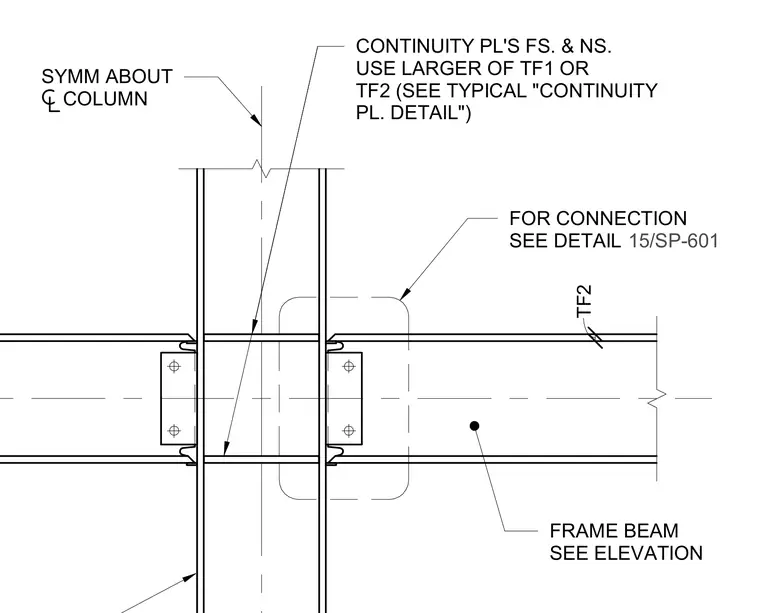
Continuity plates are positioned on the far side and near side of the steel column flange, centered symmetrically about the column axis. The plate thickness is sized using the larger of flange thickness TF1 or TF2 referenced from the connecting members. The frame beam connects to the column web and flanges via bolted shear tabs or moment connection details referenced elsewhere in the drawings.
CONTINUITY PL'S FS. & NS. USE LARGER OF TF1 OR TF2 (SEE TYPICAL "CONTINUITY PL. DETAIL") SYMM ABOUT COLUMN TF2 FRAME BEAM SEE ELEVATION FOR CONNECTION SEE DETAIL 15/SP-601
Members view this detail in full resolution, download the CAD files (SVG, PDF), and can adapt it in the built-in CAD editor — export DXF, DWG, or PDF.
Start membership