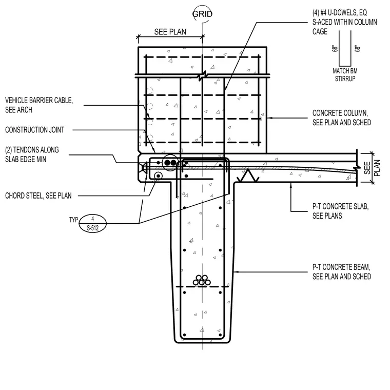
A vehicle barrier column is supported by a post-tensioned concrete slab and beam. The assembly incorporates a concrete column tied into the floor system with four number four U-dowels spaced equally within the column cage and matched to the beam stirrup. A construction joint separates the column base from the slab edge, which contains two post-tensioned tendons and chord steel configured per structural plans. Vehicle barrier cabling is coordinated with the architectural drawings at the column face.
GRID VEHICLE BARRIER CABLE, SEE ARCH P-T CONCRETE BEAM, SEE PLAN AND SCHED P-T CONCRETE SLAB, SEE PLANS CONSTRUCTION JOINT (4) #4 U-DOWELS, EQ S-ACED WITHIN COLUMN CAGE CONCRETE COLUMN, SEE PLAN AND SCHED (2) TENDONS ALONG SLAB EDGE MIN CHORD STEEL, SEE PLAN 4 S-512 TYP 68" 68" MATCH BM STIRRUP SEE PLAN SEE PLAN
Members view this detail in full resolution, download the CAD files (SVG, PDF), and can adapt it in the built-in CAD editor — export DXF, DWG, or PDF.
Start membership