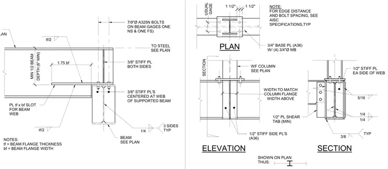
A seated beam-to-beam connection where a supported steel beam frames into a supporting beam or column. The connection incorporates a three-quarters-inch A36 base plate with four three-quarters-inch diameter machine bolts, supplemented by half-inch A36 stiffener side plates and half-inch stiffener plates on both sides of the web. Seven-eighths-inch A325N bolts fasten the beam web on standard gauges, positioned both near side and far side. Fillet welds of quarter-inch and five-sixteenth-inch sizes secure the plates as indicated by typical welding symbols. Edge distances and bolt spacings conform to AISC specifications.
SECTION SHOWN ON PLAN THUS: SECTION PLAN ELEVATION WF COLUMN SEE PLAN NOTE: FOR EDGE DISTANCE AND BOLT SPACING, SEE AISC SPECIFICATIONS,TYP 1/2" STIFF SIDE PL'S (A36) 1/2" PL SHEAR TAB (MIN) 3/4" BASE PL (A36) W/ (4) 3/4"Ø MB 1/2" STIFF PL EA SIDE OF WEB 3/8 TYP 1/4 1/4 5/16 WIDTH ABOVE WIDTH TO MATCH COLUMN FLANGE 1 1/2" 1 1/2" GAGE USUAL NOTES: tf = BEAM FLANGE THICKNESS bf = BEAM FLANGE WIDTH PL tf x bf SLOT FOR BEAM WEB BEAM SEE PLAN TO STEEL SEE PLAN SEE PLAN 3/8" STIFF PL'S CENTERED AT WEB OF SUPPORTED BEAM 3/8" STIFF PL BOTH SIDES 7/8"Ø A325N BOLTS ON BEAM GAGES ONE NS & ONE FS) 1.75 bf tf/2 DEPTH (6" MIN) MIN 1/2 BEAM 1/4 3 SIDES TYP tf/2
Members view this detail in full resolution, download the CAD files (SVG, PDF), and can adapt it in the built-in CAD editor — export DXF, DWG, or PDF.
Start membership