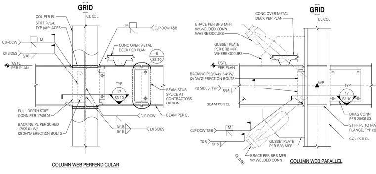
A braced frame beam splice connection is detailed in two orientations relative to the column web. The left portion presents the column web perpendicular condition featuring a full-depth stiffener connection with a backing plate attached via two 3/4-inch-diameter erection bolts, complete with complete joint penetration welds at the top and bottom flanges and 5/16-inch fillet welds on three sides typical. The right portion presents the column web parallel condition incorporating a gusset plate and brace per the buckling-restrained brace manufacturer with welded connections, along with a backing plate measuring 3/8" x 4" x 1'-4" and a beam stub splice option.
CONC OVER METAL DECK PER PLAN COLUMN WEB PERPENDICULAR BEAM PER EL FULL DEPTH STIFF CONN PER 17/S5.01 BACKING PL PER SCHED 17/S5.01 W/ (2) 3/4"Ø ERECTION BOLTS T/STL PER PLAN COL PER EL STIFF PL3/4, TYP (4) PLACES M CJP-DCW T&B CJP-DCW 5/16 5/16 (3) SIDES 5/16 (3) SIDES M CJP-DCW S3.10 17 TYP S3.10 8 GRID CL COL BEAM STUB SPLICE AT CONTRACTORS OPTION GRID CONC OVER METAL DECK PER PLAN CL COL BACKING PL3/8x4x1'-4" W/ (2) 3/4"Ø ERECTION BOLTS T/STL PER PLAN BEAM PER EL WP COLUMN WEB PARALLEL STIFF PL TO MATCH BEAM FLANGE, TYP (2) PLACES COL PER EL DRAG CONN PER 20/S6.03 CJP-DCW T&B 5/16 T&B M BRACE PER BRB MFR W/ WELDED CONN CL BRB GUSSET PLATE PER BRB MFR BRACE PER BRB MFR W/ WELDED CONN WHERE OCCURS GUSSET PLATE PER BRB MFR WHERE OCCURS 5/16 (3) SIDES, TYP S3.10 17 TYP
Members view this detail in full resolution, download the CAD files (SVG, PDF), and can adapt it in the built-in CAD editor — export DXF, DWG, or PDF.
Start membership