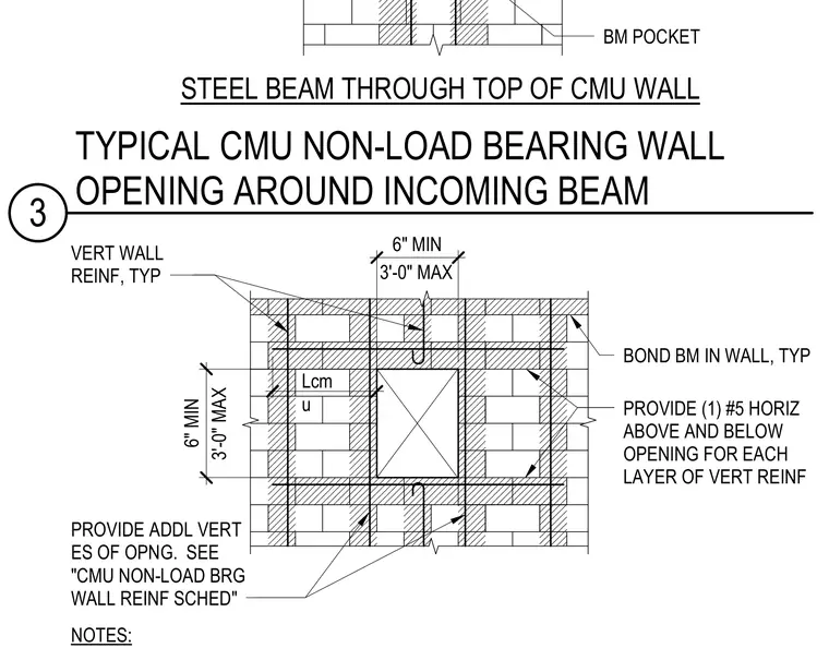
A steel beam passes through the top of a non-load-bearing concrete masonry unit wall with a beam pocket opening. Typical vertical wall reinforcement and bond beams frame the opening, supplemented by one number five horizontal bar placed above and below the opening for each layer of vertical reinforcement. Additional vertical reinforcement is provided at the edges of the opening per the concrete masonry unit non-load-bearing wall reinforcement schedule. Dimensions specify minimum clearances and maximum spacings ranging from six inches minimum to three feet maximum around the penetration.
STEEL BEAM THROUGH TOP OF CMU WALL BM POCKET VERT WALL REINF, TYP BOND BM IN WALL, TYP PROVIDE (1) #5 HORIZ ABOVE AND BELOW OPENING FOR EACH LAYER OF VERT REINF NOTES: 29 1/4" Lcm u 30 1/2" 22 7/8" 6" MIN PROVIDE ADDL VERT ES OF OPNG. SEE "CMU NON-LOAD BRG WALL REINF SCHED" 3'-0" MAX 6" MIN 3'-0" MAX 3 TYPICAL CMU NON-LOAD BEARING WALL OPENING AROUND INCOMING BEAM
Members view this detail in full resolution, download the CAD files (SVG, PDF), and can adapt it in the built-in CAD editor — export DXF, DWG, or PDF.
Start membership