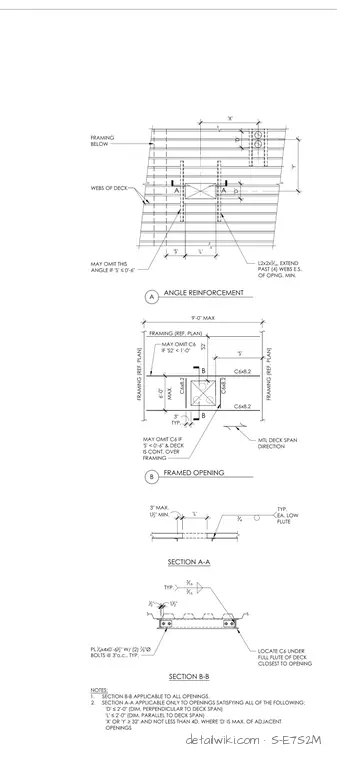
The drawing illustrates structural steel components used to reinforce openings in a metal deck system, including channel sections (C6x8.2), angle reinforcements, and framing details. Sections A-A and B-B provide specific connection requirements such as plate dimensions, bolt sizes, and weld specifications. Notes specify criteria regarding opening dimensions and deck span conditions for applying the details.
Text on the drawing
L2x2x 3 16 , EXTEND PAST (4) WEBS E.S. OF OPNG, MIN. 'S' 'D' 'Y' 'D' 'L' 'X' C6x8.2 3" TYP. 9'-0" MAX 6'-0" MAX. 'S2' C6x8.2 'S' C6x8.2 C6x8.2 SECTION B-B PL 1 4 x4x0'-6 1 2 " W/ (2) 7 8 "Ø BOLTS @ 3"o.c., TYP. 'L' SECTION A-A 3" MAX. 1 1 2 " MIN. 12 " 1 1 2 " 3 4 316 316 NOTES: 1. SECTION B-B APPLICABLE TO ALL OPENINGS. 2. SECTION A-A APPLICABLE ONLY TO OPENINGS SATISFYING ALL OF THE FOLLOWING: 'D' ≤ 2'-0" (DIM. PERPENDICULAR TO DECK SPAN) 'L' ≤ 2'-0" (DIM. PARALLEL TO DECK SPAN) 'X' OR 'Y' ≥ 32" AND NOT LESS THAN 4D, WHERE 'D' IS MAX. OF ADJACENT OPENINGS LOCATE C6 UNDER FULL FLUTE OF DECK CLOSEST TO OPENING TYP. TYP. EA. LOW FLUTE MTL DECK SPAN DIRECTION MAY OMIT C6 IF 'S' < 0'-6" & DECK IS CONT. OVER FRAMING FRAMING (REF. PLAN) FRAMING (REF. PLAN) FRAMING (REF. PLAN) MAY OMIT C6 IF 'S2' < 1'-0" MAY OMIT THIS ANGLE IF 'S' ≤ 0'-6" WEBS OF DECK FRAMING BELOW ANGLE REINFORCEMENT A FRAMED OPENING B A A B B
Members view this detail in full resolution, download the CAD files (SVG, PDF), and open any detail in the built-in CAD editor to edit and export DXF or DWG.
Sign in to subscribe