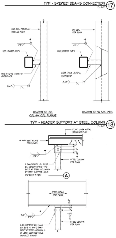
Non-bearing column to beam connections consist of hollow structural section headers and outriggers welded to steel columns with complete joint penetration welds. The header support assembly features an angle measuring 6x4x3/8 inches by 5 inches long on each side, secured with three-quarter inch diameter through bolts at the steel column through a two-inch vertical slotted hole while leaving no slot in the hollow structural section. A concrete over metal deck assembly bears upon the top plate, connected with a one-quarter inch minimum bent plate per detail 2/S0.5 and one-quarter inch fillet welds. Steel beams per plan sit above the column supports, integrated with typical one-quarter inch welds.
HSS HEADER (S.P.) HSS COL. PER PLAN (Wx COL W.O.) HSS 3 1/2"x3 1/2"x5/16" OUTRIGGER HSS HEADER (S.P.) Wx COL. PER PLAN C.J.P. 1/4" HSS3 1/2x3 1/2x5/16 OUTRIGGER HEADER AT HSS COL./Wx COL. FLANGE HEADER AT Wx COL. WEB C.J.P. 1/4" STEEL BEAM PER PLAN 1/4" TYP. L 6x4x3/8"x5" LG. (LLV) EA. SIDE W/ 3/4"Ø THRU BOLT AT STEEL COLUMN IN 2" VERT. SLOTTED HOLE (NO SLOT IN HSS) STEEL COLUMN PER PLAN 1 1/2" 2" 2 1/2" A CONC. OVER METAL DECK SEE PLAN BENT PLATE PER 2/S0.5 STEEL COLUMN PER PLAN 1/4" L 6x4x3/8"x5" LG. (LLV) EA. SIDE W/ 3/4"Ø THRU BOLT AT STEEL COLUMN IN 2" VERT. SLOTTED HOLE (NO SLOT IN HSS) 1 1/2" 2" 2 1/2" 1" = 1'-0" 18 TYP - HEADER SUPPORT AT STEEL COLUMN 1" = 1'-0" 17 TYP - SKEWED BEAMS CONNECTION 1/4" MIN.
Members view this detail in full resolution, download the CAD files (SVG, PDF), and can adapt it in the built-in CAD editor — export DXF, DWG, or PDF.
Start membership