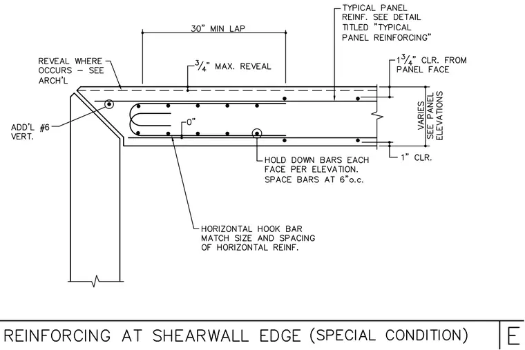
Reinforcing layout at a concrete shearwall edge for a special condition. The assembly features a horizontal hook bar matching the size and spacing of horizontal reinforcement, tied with additional number six vertical bars at the corner. Hold down bars are placed on each face per elevation with space bars at six inches on center. The drawing notes a thirty inch minimum lap, a zero to three-quarter inch maximum reveal where occurs, and a one and three-quarter inch clearance from the panel face with one inch clearance at the bottom.
Members view this detail in full resolution, download the CAD files (SVG, PDF), and can adapt it in the built-in CAD editor — export DXF, DWG, or PDF.
Start membership