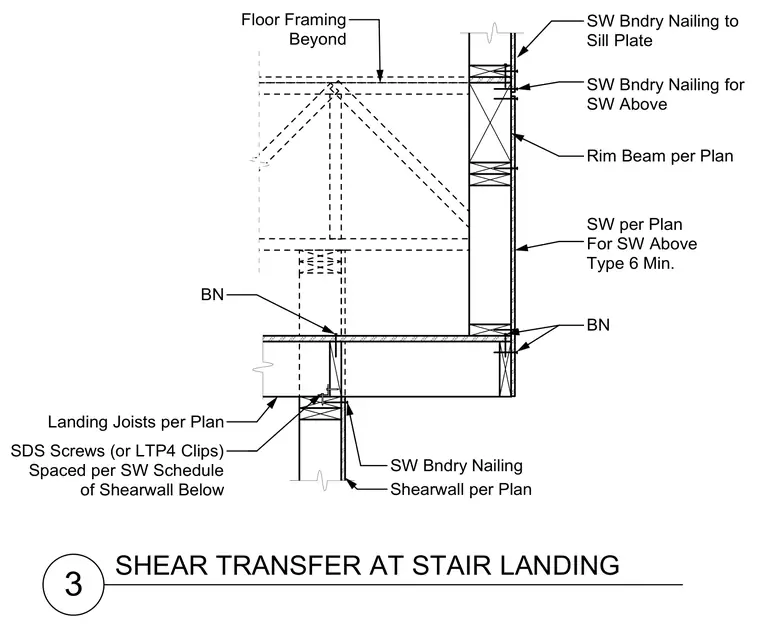
Shear transfer at a stair landing utilizes landing joists and a rim beam framed against shear walls. Boundary nailing for the shear wall above is secured to the sill plate and rim beam per plan. Landing joists tie into the support assembly using SDS screws or LTP4 clips spaced according to the shear wall schedule below. Floor framing extends beyond the shear wall with boundary nailing specified as Type 6 minimum.
3 SHEAR TRANSFER AT STAIR LANDING Shearwall per Plan SW Bndry Nailing SDS Screws (or LTP4 Clips) Spaced per SW Schedule of Shearwall Below Landing Joists per Plan Rim Beam per Plan SW Bndry Nailing for SW Above SW Bndry Nailing to Sill Plate BN BN Floor Framing Beyond SW per Plan For SW Above Type 6 Min.
Members view this detail in full resolution, download the CAD files (SVG, PDF), and can adapt it in the built-in CAD editor — export DXF, DWG, or PDF.
Start membership