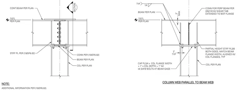
A continuous steel beam runs over a wide flange steel column sized per plan. A three-quarter-inch thick cap plate matching the column flange width plus one inch by column depth plus one inch is bolted to the column flange with four three-quarter-inch diameter bolts at the beam gage. Partial-height three-eighths-inch stiffener plates are welded to both sides, matching the beam flange width and aligned with the column flanges. A perpendicular beam connection uses a shear tab extended to the bottom flange with a one-quarter-inch fillet weld.
SECTION COL PER PLAN CONN PER [19/SF6.02] CONT BEAM PER PLAN STIFF PL PER [19/SF6.02] BEAM PER PLAN T/STL PER PLAN ADDITIONAL INFORMATION PER [19/SF6.02]. NOTE: COL PER PLAN PARTIAL HEIGHT STIFF PL3/8 BOTH SIDES, MATCH BEAM FLANGE WIDTH, ALIGNED W/ COL FLANGES, TYP TYP 2" CAP PL3/4 x COL FLANGE WIDTH + 1" x COL DEPTH + 1" W/ (4) 3/4"Ø BOLTS AT BEAM GAGE BEAM PER PLAN 1/4 TYP MAX 2" CONN FOR PERP BEAM PER [05210] W/ SHEAR TAB EXTENDED TO BOT FLANGE T/STL PER PLAN COLUMN WEB PARALLEL TO BEAM WEB
Members view this detail in full resolution, download the CAD files (SVG, PDF), and can adapt it in the built-in CAD editor — export DXF, DWG, or PDF.
Start membership