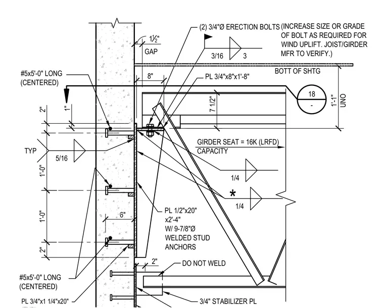
A steel truss girder bears against a concrete wall via a half-inch by 20-inch by 2-foot-4-inch embedded steel plate anchored with nine 7/8-inch diameter welded studs. A 3/4-inch by 8-inch by 1-foot-8-inch plate forms the girder seat, designed for a 16-kip LRFD capacity, connected with a 3/16-inch fillet weld and two 3/4-inch diameter erection bolts. A 3/4-inch stabilizer plate connects below, left unwelded to the girder as noted. Reinforcing includes centered number 5 bars at 5 feet long embedded in the concrete. A 1/4-inch fillet weld secures the seat assembly, and a 5/16-inch fillet weld attaches the embed plate.
1" 2" 2" PL 3/4"x1 1/4"x20" 1'-0" 1'-0" 2" DO NOT WELD 3/4" STABILIZER PL PL 3/4"x8"x1'-8" (2) 3/4"Ø ERECTION BOLTS 1'-1" UNO PL 1/2"x20" x2'-4" W/ 9-7/8"Ø WELDED STUD ANCHORS 1 12 " 6" GAP GIRDER SEAT = 16K (LRFD) CAPACITY BOTT OF SHTG #5x5'-0" LONG (CENTERED) #5x5'-0" LONG (CENTERED) 18 - * 1/4 1/4 3/16 3 5/16 TYP 8" 7 1/2" (INCREASE SIZE OR GRADE OF BOLT AS REQUIRED FOR WIND UPLIFT. JOIST/GIRDER MFR TO VERIFY.)
Members view this detail in full resolution, download the CAD files (SVG, PDF), and can adapt it in the built-in CAD editor — export DXF, DWG, or PDF.
Start membership