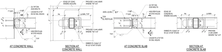
An elevator spreader beam hollow structural section connects to a concrete wall or concrete slab via an embed plate measuring half-inch by eight inches by one foot two inches, welded with four half-inch by six-inch studs. A structural steel angle measuring L4x3x5/16 by zero feet six inches is attached to each side with standard slotted holes and two seven-eighth-inch diameter A325 bolts. Additional reinforcing includes number four U-bars where edge distances are restricted, and additional number four bars spaced at four inches per plan.
SECT SECT SIM 1" CLR HSS PER PLAN W/ STD HOLES AT CONCRETE WALL SECTION AT CONCRETE WALL EMBED PL1/2x8x1'-2" W/ (4) 1/2"x6" STUDS L4x3x5/16 x 0'-6" ES W/ SSL HOLES (2) 7/8" DIA A325 BOLTS HSS PER PLAN W/ STD HOLES AT CONCRETE SLAB 1/4 4" EL PER PLAN TOS ADDL (2) #4x @ 4" 2'-0" 1 1/2" 3" 1 1/2" 1/2" 1/2" TYP 1 1/2" 1 1/2" 1" CLR 1 1/2" 1 1/2" 1/4 1/2" 1/2" TYP L4x3x5/16 x 0'-6" ES W/ SSL HOLES 1 1/2" 3" 1 1/2" 2" 4" (2) 7/8" DIA A325 BOLTS 9" 9" He Ht 2" 2" 9 1/4" Ld MIN, TYP PROVIDE (1) #4 U-BAR WHERE "Ht" ≤6" PROVIDE (1) #4 U-BAR WHERE "He" ≤6" SECTION AT CONCRETE SLAB 2" 2" 5 3/4" 9 1/4" He Ld MIN EMBED PL1/2x8x1'-2" W/ (4) 1/2"x6" STUDS EDGE OF CONCRETE WHERE OCCURS PROVIDE (1) #4 U-BAR WHERE "He" ≤6" EDGE OF CONC WHERE OCCURS
Members view this detail in full resolution, download the CAD files (SVG, PDF), and can adapt it in the built-in CAD editor — export DXF, DWG, or PDF.
Start membership