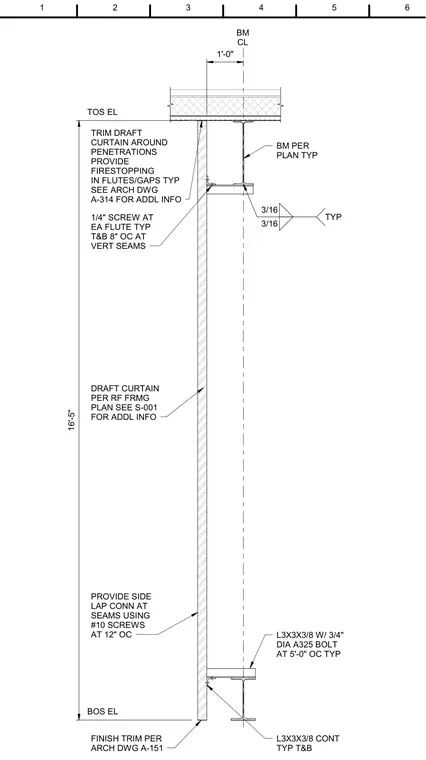
A draft curtain drops from the roof structure and is supported by structural steel beams located per the roof framing plan. Continuous L3x3x3/8 angles attach to the top and bottom of the curtain with three-quarter-inch diameter ASTM A325 bolts spaced at five feet on center, secured with three-sixteenths fillet welds typical. Side lap connections use number ten screws at twelve inches on center, and one-quarter-inch screws fasten at each flute top and bottom at eight inches on center vertically. Firestopping is provided in flutes and gaps around penetrations, and finish trim is installed per architectural drawings.
BM PER PLAN TYP 1/4" SCREW AT EA FLUTE TYP T&B 8" OC AT VERT SEAMS PROVIDE SIDE LAP CONN AT SEAMS USING #10 SCREWS AT 12" OC DRAFT CURTAIN PER RF FRMG PLAN SEE S-001 FOR ADDL INFO FINISH TRIM PER ARCH DWG A-151 BOS EL TOS EL 3/16 3/16 TYP L3X3X3/8 W/ 3/4" DIA A325 BOLT AT 5'-0" OC TYP L3X3X3/8 CONT TYP T&B 16'-5" 1'-0" BM CL TRIM DRAFT CURTAIN AROUND PENETRATIONS PROVIDE FIRESTOPPING IN FLUTES/GAPS TYP SEE ARCH DWG A-314 FOR ADDL INFO 1 3 5 2 4 6
Members view this detail in full resolution, download the CAD files (SVG, PDF), and can adapt it in the built-in CAD editor — export DXF, DWG, or PDF.
Start membership