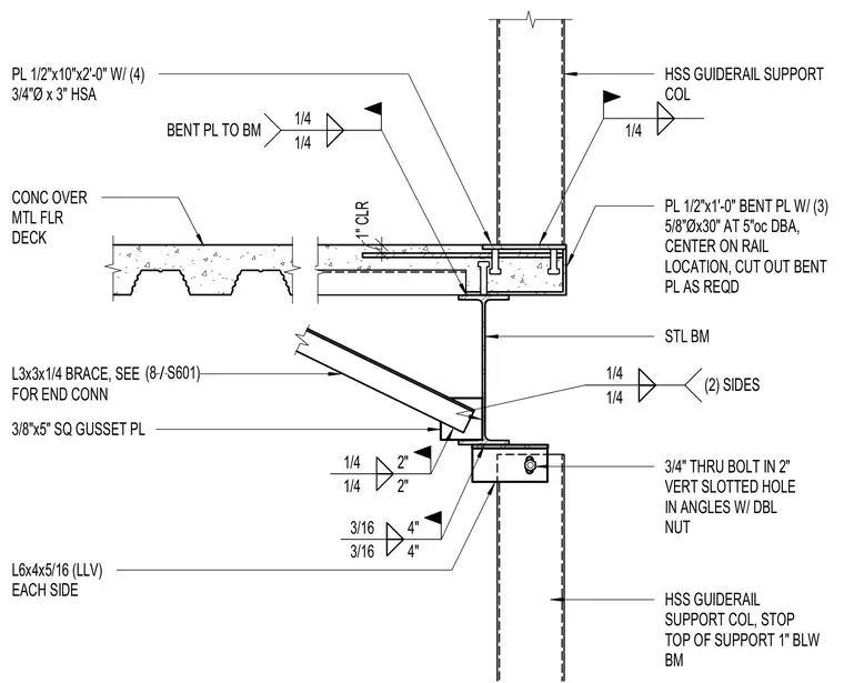
A structural steel elevator guide rail support column is anchored beneath a concrete slab over metal floor deck and steel beam assembly. The hollow structural section guide rail support column is secured at the top with a 1/2-inch by 10-inch by 2-foot plate fastened using four 3/4-inch diameter by 3-inch heavy-duty anchor bolts, and a 1/2-inch by 1-foot bent plate with three 5/8-inch diameter by 30-inch deformed bar anchors at 5 inches on center. A diagonal brace consisting of an L3x3x1/4 angle connects to the steel beam web using a 3/8-inch by 5-inch square gusset plate welded with 1/4-inch fillet welds on two sides. At the lower support column, L6x4x5/16 angles are welded on each side with 3/16-inch fillet welds and connected using a 3/4-inch through bolt in a 2-inch vertical slotted hole with double nuts. The top of the lower support column stops 1 inch below the steel beam.
HSS GUIDERAIL SUPPORT COL, STOP TOP OF SUPPORT 1" BLW BM STL BM 3/4" THRU BOLT IN 2" VERT SLOTTED HOLE IN ANGLES W/ DBL NUT HSS GUIDERAIL SUPPORT COL PL 1/2"x10"x2'-0" W/ (4) 3/4"Ø x 3" HSA PL 1/2"x1'-0" BENT PL W/ (3) 5/8"Øx30" AT 5"oc DBA, CENTER ON RAIL LOCATION, CUT OUT BENT PL AS REQD CONC OVER MTL FLR DECK L6x4x5/16 (LLV) EACH SIDE L3x3x1/4 BRACE, SEE FOR END CONN 3/8"x5" SQ GUSSET PL 1/4 1/4 (2) SIDES 1/4 1/4 1/4 BENT PL TO BM 3/16 3/16 4" 4" 1/4 1/4 2" 2" 1" CLR / (8 S601)
Members view this detail in full resolution, download the CAD files (SVG, PDF), and can adapt it in the built-in CAD editor — export DXF, DWG, or PDF.
Start membership