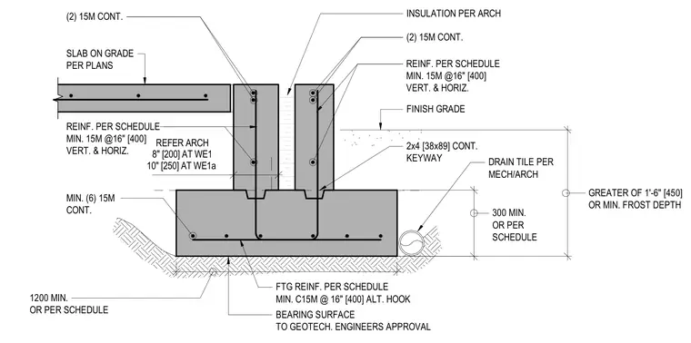
A concrete foundation wall is supported by a continuous concrete footing with a slab on grade bearing connection. The footing features minimum six fifteen-millimeter continuous reinforcing bars, with minimum C fifteen-millimeter bars at sixteen-inch alternate hooks resting on a bearing surface approved by the geotechnical engineer. The foundation walls incorporate vertical and horizontal minimum fifteen-millimeter reinforcing bars spaced at sixteen inches, continuous top reinforcing bars per schedule, and a continuous two-by-four keyway at the footing joint. Insulation is provided per architectural specifications, and a perimeter drain tile is located adjacent to the exterior footing per mechanical and architectural coordination. Finish grade and frost depth dimensions are designated with minimum clearance requirements.
SLAB ON GRADE PER PLANS MIN. 15M @16" [400] VERT. & HORIZ. MIN. (6) 15M CONT. 1200 MIN. OR PER SCHEDULE (2) 15M CONT. 300 MIN. OR PER SCHEDULE GREATER OF 1'-6" [450] OR MIN. FROST DEPTH FTG REINF. PER SCHEDULE MIN. C15M @ 16" [400] ALT. HOOK BEARING SURFACE TO GEOTECH. ENGINEERS APPROVAL FINISH GRADE DRAIN TILE PER MECH/ARCH REINF. PER SCHEDULE MIN. 15M @16" [400] VERT. & HORIZ. 2x4 [38x89] CONT. KEYWAY 10" [250] AT WE1a REFER ARCH 8" [200] AT WE1 (2) 15M CONT. REINF. PER SCHEDULE MIN. 15M @16" [400] VERT. & HORIZ. REINF. PER SCHEDULE MIN. 15M @16" [400] VERT. & HORIZ. INSULATION PER ARCH
Members view this detail in full resolution, download the CAD files (SVG, PDF), and can adapt it in the built-in CAD editor — export DXF, DWG, or PDF.
Start membership