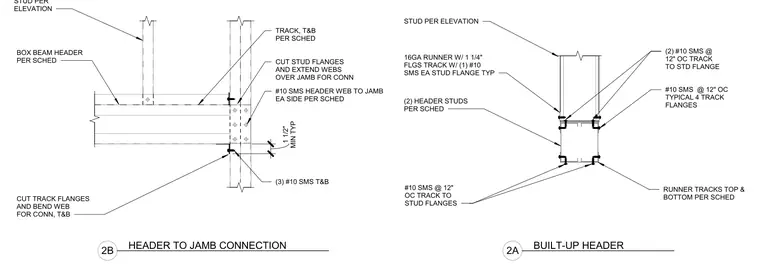
A built-up box beam header is framed using runner tracks top and bottom per schedule, with stud flanges cut and webs extended over the jamb for connection. The header web connects to the jamb with number ten self-tapping metal screws on each side per schedule, supplemented by three number ten screws top and bottom. Stud flanges are secured to the track with number ten self-tapping metal screws at twelve inches on center typical across all four track flanges. The sixteen gauge runner track features one and one-quarter inch flanges attached to each stud flange with one number ten self-tapping metal screw typical.
STUD PER ELEVATION 16GA RUNNER W/ 1 1/4" FLGS TRACK W/ (1) #10 SMS EA STUD FLANGE TYP (2) HEADER STUDS PER SCHED (2) #10 SMS @ 12" OC TRACK TO STD FLANGE #10 SMS @ 12" OC TYPICAL 4 TRACK FLANGES RUNNER TRACKS TOP & BOTTOM PER SCHED #10 SMS @ 12" OC TRACK TO STUD FLANGES TRACK, T&B PER SCHED #10 SMS HEADER WEB TO JAMB EA SIDE PER SCHED BOX BEAM HEADER PER SCHED (3) #10 SMS T&B STUD PER ELEVATION CUT STUD FLANGES AND EXTEND WEBS OVER JAMB FOR CONN CUT TRACK FLANGES AND BEND WEB FOR CONN, T&B MIN TYP 1 1/2" 2A BUILT-UP HEADER 2B HEADER TO JAMB CONNECTION
Members view this detail in full resolution, download the CAD files (SVG, PDF), and can adapt it in the built-in CAD editor — export DXF, DWG, or PDF.
Start membership