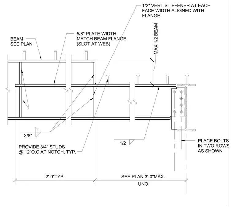
A typical steel beam notch assembly features a five-eighths inch plate with a width matching the beam flange and slotted at the web. A one-half inch vertical stiffener is provided at each face with its width aligned with the flange. Three-quarter inch studs are spaced at twelve inches on center typically throughout the notched region. The beam connects to a supporting member via bolts placed in two rows as shown, supported by weld configurations including three-eighths inch and one-half inch welds. Dimensions indicate a typical spacing of two feet and a maximum of three feet unless otherwise noted.
PLACE BOLTS IN TWO ROWS AS SHOWN BEAM SEE PLAN 5/8" PLATE WIDTH MATCH BEAM FLANGE (SLOT AT WEB) MAX 1/2 BEAM 2'-0"TYP. UNO SEE PLAN 3'-0"MAX. 3/8" 1/2 1/2" VERT STIFFENER AT EACH FACE WIDTH ALIGNED WITH FLANGE PROVIDE 3/4" STUDS @ 12"O.C AT NOTCH, TYP.
Members view this detail in full resolution, download the CAD files (SVG, PDF), and can adapt it in the built-in CAD editor — export DXF, DWG, or PDF.
Start membership