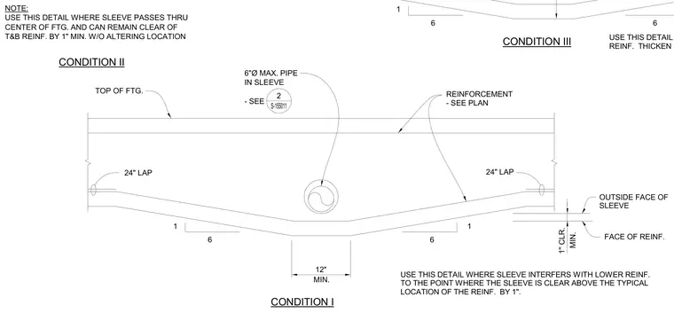
Reinforcement adjustments in a concrete footing occur where a pipe sleeve interferes with the lower reinforcing steel. The profile shows the footing bottom stepped upward with a one-to-six slope maintaining a twelve-inch minimum flat section beneath a six-inch maximum pipe in a sleeve. Reinforcement is lapped twenty-four inches on either side of the transition while maintaining a one-inch minimum clearance from the outside face of the sleeve to the face of the reinforcement. Notes specify that this condition is used when the sleeve interferes with lower reinforcing to the point where the sleeve sits clear above the typical location of the reinforcement by one inch.
TOP OF FTG. FACE OF REINF. NOTE: USE THIS DETAIL WHERE SLEEVE PASSES THRU CENTER OF FTG. AND CAN REMAIN CLEAR OF T&B REINF. BY 1" MIN. W/O ALTERING LOCATION USE THIS DETAIL WHERE SLEEVE INTERFERS W/ TOP REINF. THICKEN FTG. TO MAINTAIN DEPTH OF TOP REINF. USE THIS DETAIL WHERE SLEEVE INTERFERS WITH LOWER REINF. TO THE POINT WHERE THE SLEEVE IS CLEAR ABOVE THE TYPICAL LOCATION OF THE REINF. BY 1". REINFORCEMENT - SEE PLAN OUTSIDE FACE OF SLEEVE 6"Ø MAX. PIPE IN SLEEVE - SEE 2 S-155011 12" MIN. 1" CLR. MIN. CONDITION II 24" LAP 24" LAP 1 6 1 6 CONDITION I 6 6 1 CONDITION III
Members view this detail in full resolution, download the CAD files (SVG, PDF), and can adapt it in the built-in CAD editor — export DXF, DWG, or PDF.
Start membership