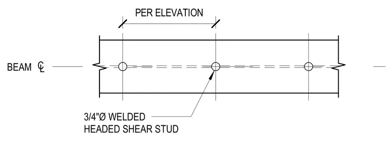
This assembly consists of three-quarter inch diameter welded headed shear studs installed in a single row along the centerline of a steel beam. The spacing between the shear studs is determined per the project elevation drawings. The studs are positioned along the beam longitudinal axis to provide composite action between the steel beam and the concrete slab.
Members view this detail in full resolution, download the CAD files (SVG, PDF), and can adapt it in the built-in CAD editor — export DXF, DWG, or PDF.
Start membership