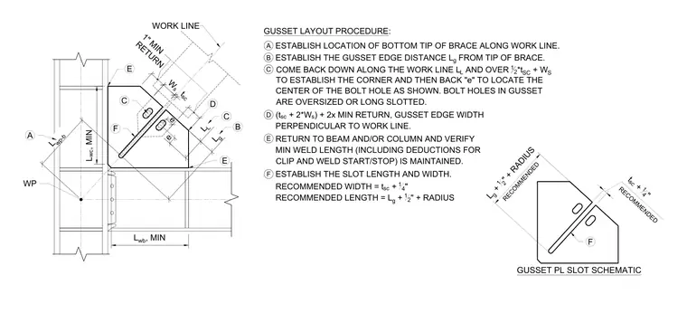
This structural detail provides a step-by-step layout procedure for configuring a gusset plate connection with a slot for bracing. The process begins by establishing the location of the bottom tip of the brace along the work line, followed by laying out edge distances and bolt hole locations with oversized or long slotted holes. Weld return lengths and edge widths perpendicular to the work line are detailed alongside specific geometric formulas for recommended slot length and width based on plate thickness.
E B A 1" MIN RETURN WP WORK LINE W s t sc L wc , MIN L wb , MIN L g L L e C e D C F A ESTABLISH LOCATION OF BOTTOM TIP OF BRACE ALONG WORK LINE. GUSSET LAYOUT PROCEDURE: B ESTABLISH THE GUSSET EDGE DISTANCE L g FROM TIP OF BRACE. C COME BACK DOWN ALONG THE WORK LINE L L AND OVER 12 * t SC + W S T O ESTABLISH THE CORNER AND THEN BACK "e" TO LOCATE THE CENTER OF THE BOLT HOLE AS SHOWN. BOLT HOLES IN GUSSET ARE OVERSIZED OR LONG SLOTTED. L wp-b (t sc + 2*W s ) + 2x MIN RETURN, GUSSET EDGE WIDTH PERPENDICULAR TO WORK LINE. D E ESTABLISH THE SLOT LENGTH AND WIDTH. RECOMMENDED LENGTH = L g + 12 " + RADIUS RECOMMENDED WIDTH = t sc + 14 " E L g + 12 " + RADIUS RECOMMENDED t sc + 1 4 " RECOMMENDED F F GUSSET PL SLOT SCHEMATIC RETURN TO BEAM AND/OR COLUMN AND VERIFY MIN WELD LENGTH (INCLUDING DEDUCTIONS FOR CLIP AND WELD START/STOP) IS MAINTAINED.
Members view this detail in full resolution, download the CAD files (SVG, PDF), and can adapt it in the built-in CAD editor — export DXF, DWG, or PDF.
Start membership