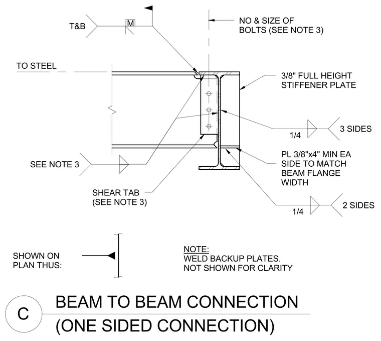
A supported steel beam connects to the supporting beam web through a single plate shear tab secured with bolts sized per note three. A three-eighths-inch full-height stiffener plate is welded to the supporting beam web with a quarter-inch fillet weld on three sides. Additional three-eighths by four-inch minimum plates sized to match the beam flange width are welded top and bottom with a quarter-inch fillet weld on two sides. Weld backup plates are welded as noted but omitted from the drawing for clarity.
BEAM TO BEAM CONNECTION C (ONE SIDED CONNECTION) SHOWN ON PLAN THUS: TO STEEL NOTE: WELD BACKUP PLATES. NOT SHOWN FOR CLARITY NO & SIZE OF BOLTS (SEE NOTE 3) SHEAR TAB (SEE NOTE 3) 3/8" FULL HEIGHT STIFFENER PLATE PL 3/8"x4" MIN EA SIDE TO MATCH BEAM FLANGE WIDTH M T&B 1/4 3 SIDES SEE NOTE 3 1/4 2 SIDES
Members view this detail in full resolution, download the CAD files (SVG, PDF), and can adapt it in the built-in CAD editor — export DXF, DWG, or PDF.
Start membership