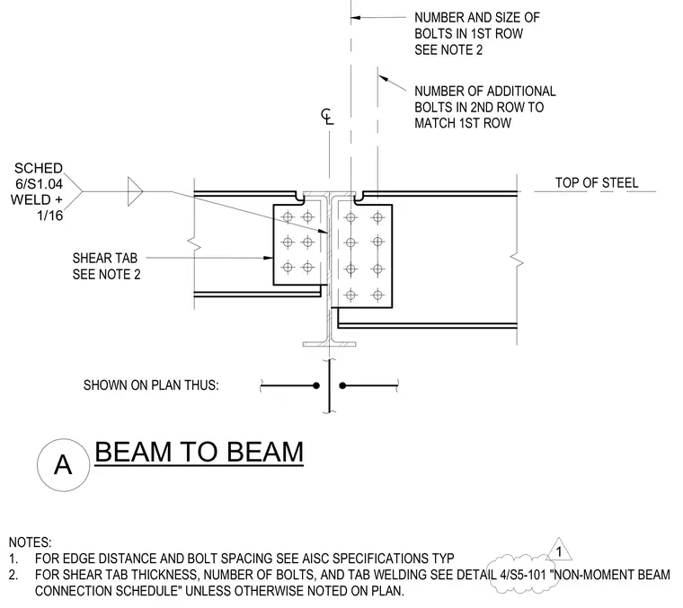
A beam-to-beam connection utilizes a shear tab welded to the supporting member and bolted to the supported beam web. The connection features rows of bolts sized according to the structural schedule, with edge distances and bolt spacings conforming to American Institute of Steel Construction specifications. The shear tab is welded to the supporting girder web with a fillet weld size determined by schedule. The top flange of the supported beam is notched or coped to align with the top of steel elevation of the supporting member.
NOTES: 1. FOR EDGE DISTANCE AND BOLT SPACING SEE AISC SPECIFICATIONS TYP 2. FOR SHEAR TAB THICKNESS, NUMBER OF BOLTS, AND TAB WELDING SEE DETAIL 4/S5-101 "NON-MOMENT BEAM CONNECTION SCHEDULE" UNLESS OTHERWISE NOTED ON PLAN. SHEAR TAB SEE NOTE 2 TOP OF STEEL NUMBER AND SIZE OF BOLTS IN 1ST ROW SEE NOTE 2 A BEAM TO BEAM SHOWN ON PLAN THUS: NUMBER OF ADDITIONAL BOLTS IN 2ND ROW TO MATCH 1ST ROW SCHED 6/S1.04 WELD + 1/16 1
Members view this detail in full resolution, download the CAD files (SVG, PDF), and can adapt it in the built-in CAD editor — export DXF, DWG, or PDF.
Start membership