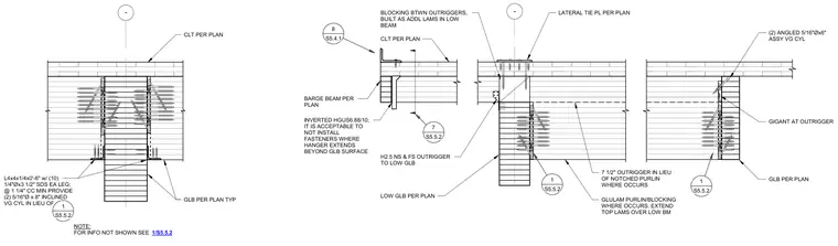
An out-of-plane connector for a mass timber roof assembly comprises cross-laminated timber panels supported by glulam beams. The connection incorporates a structural steel angle measuring four by four by one-fourth inches by zero feet six inches, fastened with ten one-fourth-inch diameter by three-and-one-half-inch self-drilling screws on each leg at one-and-one-quarter-inch center-to-center minimum spacing. Additional fasteners include two five-sixteenth-inch diameter by eight-inch inclined self-tapping wood screws in lieu of glulam rivets per plan. The assembly features an inverted concealed face mount hanger with fasteners omitted where the hanger extends beyond the glulam surface. Outriggers, blocking built as additional laminations in low beams, lateral tie plates, and angled screws secure the framing components.
- L4x4x1/4x0'-6" w/ (10) 1/4"Øx3 1/2" SDS EA LEG; @ 1 1/4" CC MIN PROVIDE (2) 5/16"Ø x 8" INCLINED VG CYL IN LIEU OF GLB PER PLAN TYP NOTE: FOR INFO NOT SHOWN SEE 1/S5.5.2 CLT PER PLAN 1 S5.5.2 - BARGE BEAM PER PLAN CLT PER PLAN INVERTED HGUS6.88/10; IT IS ACCEPTABLE TO NOT INSTALL FASTENERS WHERE HANGER EXTENDS BEYOND GLB SURFACE H2.5 NS & FS OUTRIGGER TO LOW GLB LOW GLB PER PLAN GLULAM PURLIN/BLOCKING WHERE OCCURS. EXTEND TOP LAMS OVER LOW BM 1 S5.5.2 1 S5.5.2 BLOCKING BTWN OUTRIGGERS, BUILT AS ADDL LAMS IN LOW BEAM LATERAL TIE PL PER PLAN GLB PER PLAN 7 1/2" OUTRIGGER IN LIEU OF NOTCHED PURLIN WHERE OCCURS (2) ANGLED 5/16"Øx6" ASSY VG CYL GIGANT AT OUTRIGGER 7 S5.5.2 8 S5.4.1
Members view this detail in full resolution, download the CAD files (SVG, PDF), and can adapt it in the built-in CAD editor — export DXF, DWG, or PDF.
Start membership