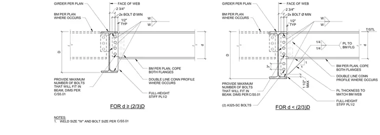
A supported steel beam connects to a supporting girder web using a shear plate welded to the girder face and bolted to the beam web with two A325-SC bolts minimum. The beam flanges are coped top and bottom to clear the girder, with a full-height stiffener plate matching the beam web thickness welded between the flanges. Fillet welds secure the stiffener and connection plates to the framing members per the sizes specified on the drawings.
GIRDER PER PLAN BM PER PLAN WHERE OCCURS PROVIDE MAXIMUM NUMBER OF BOLTS THAT WILL FIT IN BEAM, DIMS PER BM PER PLAN, COPE BOTH FLANGES FULL-HEIGHT STIFF PL1/2 W W NOTES: 1. WELD SIZE "W" AND BOLT SIZE PER 1 1 GIRDER PER PLAN BM PER PLAN WHERE OCCURS PROVIDE MAXIMUM NUMBER OF BOLTS THAT WILL FIT IN BEAM, DIMS PER W W 1/4 1/4 PL TO BM FLG BM PER PLAN, COPE BOTH FLANGES FULL-HEIGHT STIFF PL1/2 PL THICKNESS TO MATCH BM WEB MAX 1 1/2" 2x BOLT Ø MIN TYP 1/2" TYP 1/2" 2x BOLT Ø MIN 3" D D FOR d ≥(2/3)D FOR d < (2/3)D d d (2) A325-SC BOLTS DOUBLE LINE CONN PROFILE WHERE OCCURS DOUBLE LINE CONN PROFILE WHERE OCCURS 2 3/4" FACE OF WEB FACE OF WEB 2 3/4" C/S5.01 C/S5.01 C/S5.01
Members view this detail in full resolution, download the CAD files (SVG, PDF), and can adapt it in the built-in CAD editor — export DXF, DWG, or PDF.
Start membership