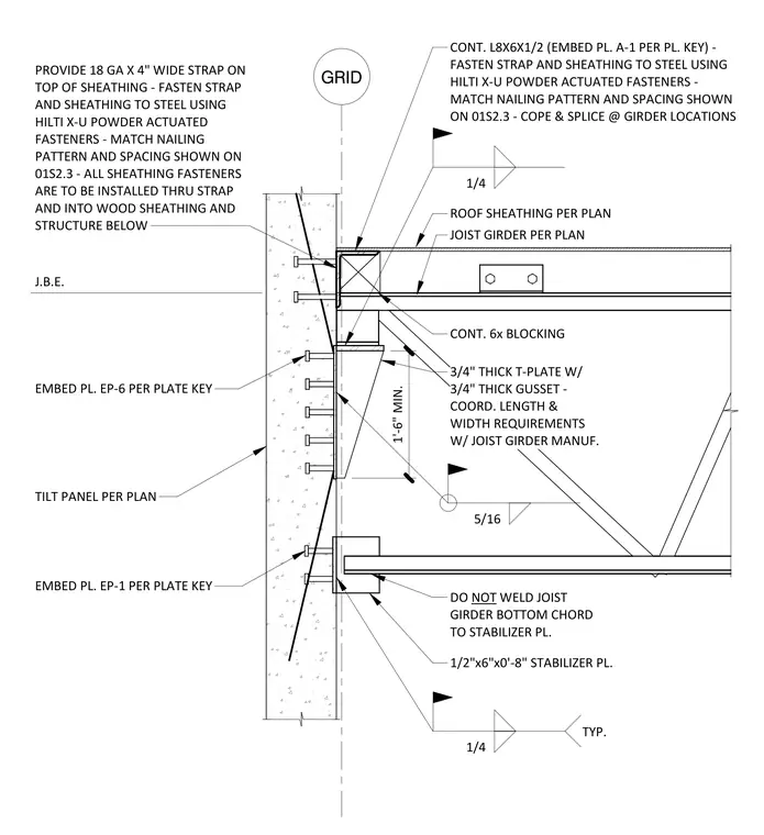
The joist girder is supported at the tilt-up concrete panel by a three-quarter-inch thick T-plate with a three-quarter-inch thick gusset, designated as embed plate EP-6. A continuous L8x6x1/2 angle, designated as embed plate A-1, supports the roof sheathing and continuous 6x blocking at the top of the panel. An 18-gauge by 4-inch wide steel strap is installed over the roof sheathing and fastened to the steel angle using Hilti X-U powder-actuated fasteners, matching the nailing pattern specified on sheet 01S2.3. At the bottom chord, a 1/2-inch by 6-inch by 8-inch stabilizer plate is attached to embed plate EP-1, but the joist girder bottom chord is left unwelded to this stabilizer plate. All fillet welds are specified as 1/4-inch or 5/16-inch as indicated.
1 3/4" THICK T-PLATE W/ 3/4" THICK GUSSET - COORD. LENGTH & WIDTH REQUIREMENTS W/ JOIST GIRDER MANUF. GRID TILT PANEL PER PLAN EMBED PL. EP-6 PER PLATE KEY J.B.E. JOIST GIRDER PER PLAN ROOF SHEATHING PER PLAN DO NOT WELD JOIST GIRDER BOTTOM CHORD TO STABILIZER PL. EMBED PL. EP-1 PER PLATE KEY CONT. 6x BLOCKING 1/4 5/16 CONT. L8X6X1/2 (EMBED PL. A-1 PER PL. KEY) - FASTEN STRAP AND SHEATHING TO STEEL USING HILTI X-U POWDER ACTUATED FASTENERS - MATCH NAILING PATTERN AND SPACING SHOWN ON 01S2.3 - COPE & SPLICE @ GIRDER LOCATIONS PROVIDE 18 GA X 4" WIDE STRAP ON TOP OF SHEATHING - FASTEN STRAP AND SHEATHING TO STEEL USING HILTI X-U POWDER ACTUATED FASTENERS - MATCH NAILING PATTERN AND SPACING SHOWN ON 01S2.3 - ALL SHEATHING FASTENERS ARE TO BE INSTALLED THRU STRAP AND INTO WOOD SHEATHING AND STRUCTURE BELOW 1'-6" MIN.
Members view this detail in full resolution, download the CAD files (SVG, PDF), and can adapt it in the built-in CAD editor — export DXF, DWG, or PDF.
Start membership