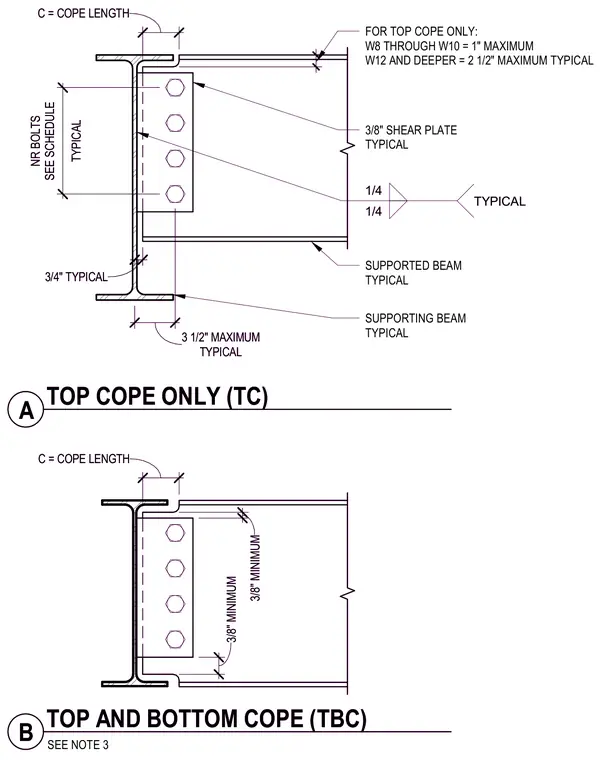
The assembly details a supported steel beam framing into a supporting beam using a three-eighth-inch shear plate welded with quarter-inch fillet welds and connected with bolts governed by the schedule. The supported beam features flange copes with specified cope lengths, including a top cope only detail and a top and bottom cope detail. Maximum cope lengths are limited to one inch for W8 through W10 shapes and two and a half inches for W12 and deeper shapes. Clearances and minimum dimensions of three-eighths inch are maintained at the flange cuts.
3/8" SHEAR PLATE TYPICAL 1/4 1/4 TYPICAL TYPICAL 3 1/2" MAXIMUM TYPICAL NR BOLTS SEE SCHEDULE 0' - 1" FOR TOP COPE ONLY: W8 THROUGH W10 = 1" MAXIMUM W12 AND DEEPER = 2 1/2" MAXIMUM TYPICAL 3/4" TYPICAL SUPPORTED BEAM TYPICAL SUPPORTING BEAM TYPICAL C = COPE LENGTH C = COPE LENGTH 3/8" MINIMUM 3/8" MINIMUM SEE NOTE 3 A TOP COPE ONLY (TC) B TOP AND BOTTOM COPE (TBC) 3/8" SHEAR PLATE TYPICAL 1/4 1/4 TYPICAL TYPICAL 3 1/2" MAXIMUM TYPICAL NR BOLTS SEE SCHEDULE 0' - 1" FOR TOP COPE ONLY: W8 THROUGH W10 = 1" MAXIMUM W12 AND DEEPER = 2 1/2" MAXIMUM TYPICAL 3/4" TYPICAL SUPPORTED BEAM TYPICAL SUPPORTING BEAM TYPICAL C = COPE LENGTH C = COPE LENGTH 3/8" MINIMUM 3/8" MINIMUM SEE NOTE 3 A TOP COPE ONLY (TC) B TOP AND BOTTOM COPE (TBC)
Members view this detail in full resolution, download the CAD files (SVG, PDF), and can adapt it in the built-in CAD editor — export DXF, DWG, or PDF.
Start membership