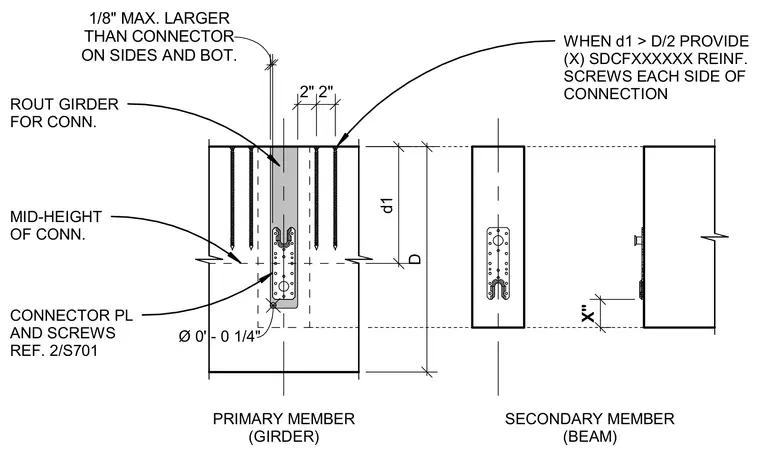
The primary member girder is routed to receive the connector plate with a maximum one-eighth inch clearance on the sides and bottom. The connector plate is secured with screws anchored on each side of the connection. When dimension d1 exceeds half of member depth D, specified reinforcement screws are provided on each side of the connection.
Ø 0' - 0 1/4" ROUT GIRDER FOR CONN. CONNECTOR PL AND SCREWS REF. 2/S701 PRIMARY MEMBER (GIRDER) X" SECONDARY MEMBER (BEAM) D d1 MID-HEIGHT OF CONN. ON SIDES AND BOT. 1/8" MAX. LARGER THAN CONNECTOR 2" 2" WHEN d1 > D/2 PROVIDE (X) SDCFXXXXXX REINF. SCREWS EACH SIDE OF CONNECTION
Members view this detail in full resolution, download the CAD files (SVG, PDF), and can adapt it in the built-in CAD editor — export DXF, DWG, or PDF.
Start membership