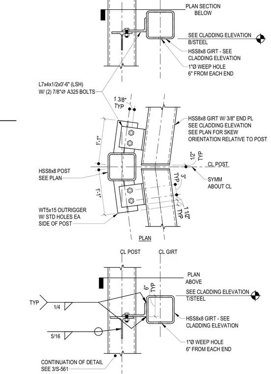
A structural connection for a cladding post and girt at level nine uses an HSS8x8 hollow structural section post and HSS8x8 girt with a three-eighths inch end plate. The girt connects back to WT5x15 outriggers welded to the post with standard holes on each side, utilizing L7x4x1x2-foot-six-inch loose steel angles secured by two seven-eighths-inch diameter A325 bolts. One-inch diameter weep holes are located six inches from each end of the girt. Fillet welds of five-sixteenths and one-quarter inch are specified at the structural junctions.
SEE CLADDING ELEVATION T/STEEL HSS8x8 GIRT - SEE CLADDING ELEVATION 1"Ø WEEP HOLE 6" FROM EACH END ABOVE PLAN TYP 6" 5/16 1/4 TYP SEE CLADDING ELEVATION B/STEEL HSS8x8 GIRT - SEE CLADDING ELEVATION 1"Ø WEEP HOLE 6" FROM EACH END PLAN SECTION BELOW 1'-1" 1'-1" TYP 1 3/8" TYP 3" TYP 1 1/2" TYP 1 1/2" L7x4x1/2x0'-6" (LSH) W/ (2) 7/8" ⌀ A325 BOLTS TYP 1/2" CL POST SYMM ABOUT CL HSS8x8 GIRT W/ 3/8" END PL SEE CLADDING ELEVATION SEE PLAN FOR SKEW ORIENTATION RELATIVE TO POST WT5x15 OUTRIGGER W/ STD HOLES EA SIDE OF POST HSS8x8 POST SEE PLAN CONTINUATION OF DETAIL SEE 3/S-561 CL POST CL GIRT PLAN
Members view this detail in full resolution, download the CAD files (SVG, PDF), and can adapt it in the built-in CAD editor — export DXF, DWG, or PDF.
Start membership