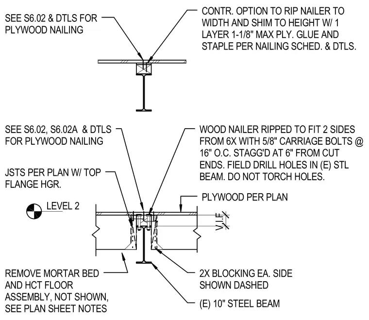
An existing ten-inch steel beam supports a floor assembly featuring wood nailers ripped to fit two sides from six-inch lumber and secured with five-eighth-inch carriage bolts at sixteen inches on center, staggered at six inches from cut ends with field-drilled holes left untorched. Joists per plan are hung with top-flange hangers adjacent to two-inch by four-inch blocking shown dashed. A plywood subfloor per plan fastens over the assembly with options to rip the nailer to width and shim to height with a single layer of maximum one-and-one-eighth-inch plywood, glued and stapled per nailing schedules.
LEVEL 2 (E) 10" STEEL BEAM PLYWOOD PER PLAN REMOVE MORTAR BED AND HCT FLOOR ASSEMBLY, NOT SHOWN, SEE PLAN SHEET NOTES JSTS PER PLAN W/ TOP FLANGE HGR. WOOD NAILER RIPPED TO FIT 2 SIDES FROM 6X WITH 5/8" CARRIAGE BOLTS @ 16" O.C. STAGG'D AT 6" FROM CUT ENDS. FIELD DRILL HOLES IN (E) STL BEAM. DO NOT TORCH HOLES. SEE S6.02, S6.02A & DTLS FOR PLYWOOD NAILING 2X BLOCKING EA. SIDE SHOWN DASHED V.I.F. CONTR. OPTION TO RIP NAILER TO WIDTH AND SHIM TO HEIGHT W/ 1 LAYER 1-1/8" MAX PLY. GLUE AND STAPLE PER NAILING SCHED. & DTLS. SEE S6.02 & DTLS FOR PLYWOOD NAILING
Members view this detail in full resolution, download the CAD files (SVG, PDF), and can adapt it in the built-in CAD editor — export DXF, DWG, or PDF.
Start membership