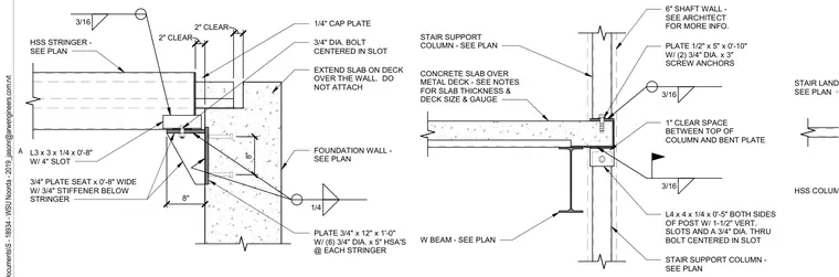
A hollow structural section stringer bears on a three-quarter-inch plate seat with a three-quarter-inch stiffener below the stringer, welded with a three-sixteenths inch fillet weld to a three-quarter-inch by twelve-inch by one-foot-zero-inch plate anchored to the concrete foundation wall with six three-quarter-inch diameter by five-inch heavy stud anchors. The concrete slab on metal deck extends over the foundation wall without direct attachment. At the stair support column, a wide-flange beam and concrete slab interface with a six-inch shaft wall utilizing a half-inch by five-inch by zero-foot-ten-inch plate with two three-quarter-inch diameter by three-inch screw anchors and a one-inch clear space between the top of the column and the bent plate. Angles measuring four by four by one-quarter inch by zero-foot-five inches on both sides of the post feature one-and-one-half-inch vertical slots and a three-quarter-inch diameter through-bolt centered in the slot.
8" 1/4 3/16 1/4" CAP PLATE 3/4" DIA. BOLT CENTERED IN SLOT EXTEND SLAB ON DECK OVER THE WALL. DO NOT ATTACH FOUNDATION WALL - SEE PLAN PLATE 3/4" x 12" x 1'-0" W/ (6) 3/4" DIA. x 5" HSA'S @ EACH STRINGER HSS STRINGER - SEE PLAN L3 x 3 x 1/4 x 0'-8" W/ 4" SLOT 3/4" PLATE SEAT x 0'-8" WIDE W/ 3/4" STIFFENER BELOW STRINGER 8" 2" CLEAR 2" CLEAR CONCRETE SLAB OVER METAL DECK - SEE NOTES FOR SLAB THICKNESS & DECK SIZE & GAUGE W BEAM - SEE PLAN 3/16 3/16 6" SHAFT WALL - SEE ARCHITECT FOR MORE INFO. STAIR SUPPORT COLUMN - SEE PLAN PLATE 1/2" x 5" x 0'-10" W/ (2) 3/4" DIA. x 3" SCREW ANCHORS 1" CLEAR SPACE BETWEEN TOP OF COLUMN AND BENT PLATE L4 x 4 x 1/4 x 0'-5" BOTH SIDES OF POST W/ 1-1/2" VERT. SLOTS AND A 3/4" DIA. THRU BOLT CENTERED IN SLOT STAIR SUPPORT COLUMN - SEE PLAN HSS COLUMN - SEE PLAN STAIR LANDING BEAM - SEE PLAN A
Members view this detail in full resolution, download the CAD files (SVG, PDF), and can adapt it in the built-in CAD editor — export DXF, DWG, or PDF.
Start membership