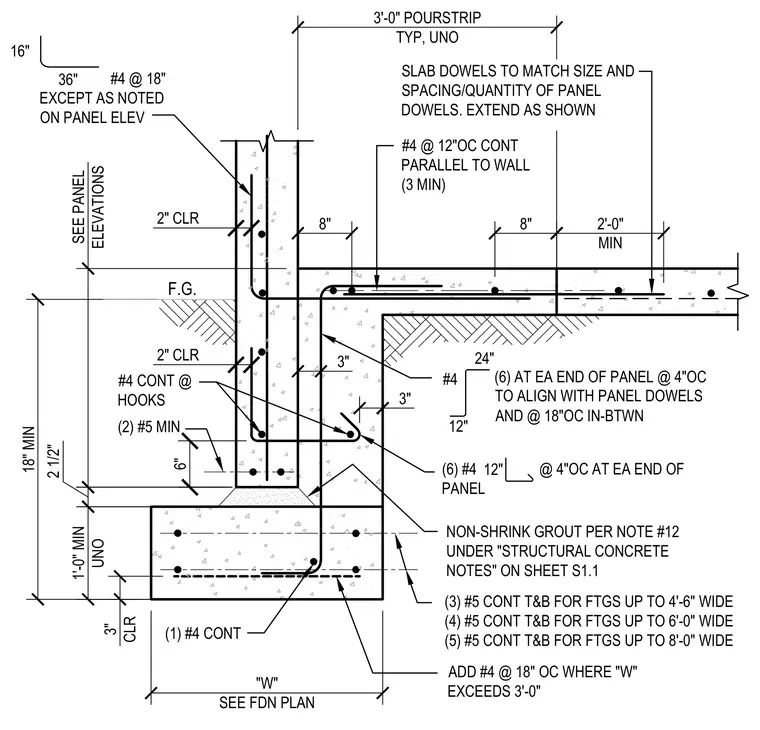
A precast concrete wall panel connects to a continuous concrete footing, incorporating a three-foot pour strip. The foundation footing is reinforced with continuous top and bottom number five bars varying from three to five bars based on footing width, along with one continuous number four bar at the bottom and three-inch concrete clear cover. Vertical dowels from the footing extend into the wall panel with six number four dowels at four inches on center at each end of the panel and eighteen inches on center in between. The wall panel features number four bars at eighteen inches on center and continuous horizontal reinforcement, maintaining two-inch clear cover. Slab dowels match the size, spacing, and quantity of the panel dowels and extend into the adjacent slab. Non-shrink grout is placed beneath the wall panel per structural notes.
8" 18" MIN 1'-0" MIN UNO SEE PANEL ELEVATIONS 2 1/2" 2'-0" MIN SLAB DOWELS TO MATCH SIZE AND SPACING/QUANTITY OF PANEL DOWELS. EXTEND AS SHOWN 8" #4 @ 18" EXCEPT AS NOTED ON PANEL ELEV #4 @ 12"OC CONT PARALLEL TO WALL (3 MIN) 3" CLR 16" 36" (2) #5 MIN F.G. 3" 3'-0" POURSTRIP TYP, UNO 2" CLR 3" 2" CLR 6" #4 CONT @ HOOKS "W" SEE FDN PLAN (1) #4 CONT NON-SHRINK GROUT PER NOTE #12 UNDER "STRUCTURAL CONCRETE NOTES" ON SHEET S1.1 (6) AT EA END OF PANEL @ 4"OC TO ALIGN WITH PANEL DOWELS AND @ 18"OC IN-BTWN ADD #4 @ 18" OC WHERE "W" EXCEEDS 3'-0" (3) #5 CONT T&B FOR FTGS UP TO 4'-6" WIDE (4) #5 CONT T&B FOR FTGS UP TO 6'-0" WIDE (5) #5 CONT T&B FOR FTGS UP TO 8'-0" WIDE 24" 12" #4 (6) #4 @ 4"OC AT EA END OF PANEL 12"
Members view this detail in full resolution, download the CAD files (SVG, PDF), and can adapt it in the built-in CAD editor — export DXF, DWG, or PDF.
Start membership