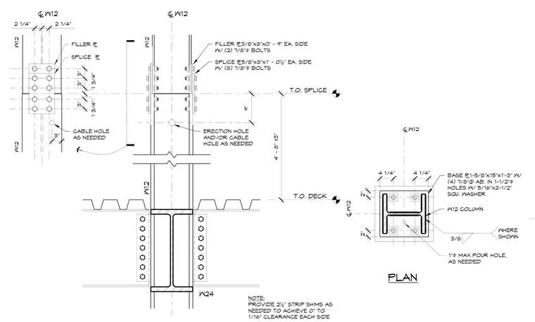
A W12 steel column base plate and column splice connection. The column base consists of a 1-5/8 inch by 15 inch by 1 foot 3 inch base plate secured with four 7/8 inch diameter anchor bolts in 1-1/2 inch diameter holes with 5/16 inch by 2-1/2 inch square washers, including a 1 inch diameter maximum pour hole as needed. The column splice features a 5/8 inch by 8 inch by 1 foot 0-1/2 inch splice plate on each side fastened with eight 7/8 inch diameter bolts, alongside a 3/8 inch by 8 inch by 0 foot 9 inch filler plate on each side fastened with two 7/8 inch diameter bolts. Erection and cable holes are provided as needed, and 2-1/2 inch strip shims are included to achieve a 0 inch to 1/16 inch clearance on each side where shown.
T.O. DECK T.O. SPLICE 4' - 8" ±3" 9" ® W12 ® W12 SPLICE ¯5/8"x8"x1' - 0½" EA. SIDE W/ (8) 7/8"ø BOLTS FILLER ¯3/8"x8"x0' - 9" EA. SIDE W/ (2) 7/8"ø BOLTS 2 1/4" 2 1/4" 3" 1 3/4" 1 3/4" 3" 3" ERECTION HOLE AND/OR CABLE HOLE AS NEEDED CABLE HOLE AS NEEDED 3" W24 W12 W12 FILLER ¯ SPLICE ¯ W12 W12 NOTE: PROVIDE 2½" STRIP SHIMS AS NEEDED TO ACHIEVE 0" TO 1/16" CLEARANCE EACH SIDE PLAN 3/8 WHERE SHOWN BASE ¯1-5/8"x15"x1'-3" W/ (4) 7/8"Ø AB. IN 1-1/2"ø HOLES W/ 5/16"x2-1/2" SQU. WASHER ® W12 ® W12 4 1/4" 2" W12 COLUMN 4 1/4" 2" 1"ø MAX POUR HOLE, AS NEEDED
Members view this detail in full resolution, download the CAD files (SVG, PDF), and can adapt it in the built-in CAD editor — export DXF, DWG, or PDF.
Start membership