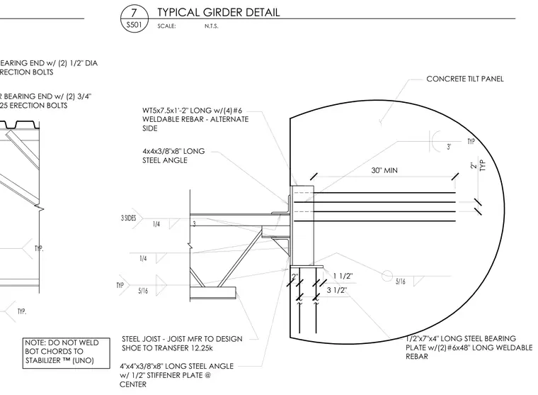
A steel joist bears onto a structural framing assembly anchored to a concrete tilt-up panel. The connection utilizes a WT5x7.5 by 1 foot 2 inches long WT-shape with four number 6 weldable rebar on alternate sides, welded to a 1/2 inch by 7 inch by 4 inch long steel bearing plate with two number 6 by 48 inch long weldable rebar embedded in the concrete. The steel joist is supported by 4x4x3/8 inch by 8 inch long steel angles, including one with a 1/2 inch stiffener plate at the center. The joist manufacturer designs the shoe to transfer 12.25 kips. The bottom chords of the joist are left unwelded to the stabilizer per the drawing note. Erection bolts include two 3/4 inch diameter A325 bolts at the girder bearing end and two 1/2 inch diameter A325 bolts at the joist bearing end.
NOTE: DO NOT WELD BOT CHORDS TO 67$%,/,=(5812 GIRDER BEARING END w/ (2) 3/4" DIA A325 ERECTION BOLTS JOIST BEARING END w/ (2) 1/2" DIA A325 ERECTION BOLTS SCALE: 7 S501 TYPICAL GIRDER DETAIL N.T.S. CONCRETE TILT PANEL 30" MIN 2" 3 1/2" 1 1/2" 1/2"x7"x4" LONG STEEL BEARING PLATE w/(2)#6x48" LONG WELDABLE REBAR WT5x7.5x1'-2" LONG w/(4)#6 WELDABLE REBAR - ALTERNATE SIDE 4x4x3/8"x8" LONG STEEL ANGLE 4"x4"x3/8"x8" LONG STEEL ANGLE w/ 1/2" STIFFENER PLATE @ CENTER STEEL JOIST - JOIST MFR TO DESIGN SHOE TO TRANSFER 12.25k 2" TYP
Members view this detail in full resolution, download the CAD files (SVG, PDF), and can adapt it in the built-in CAD editor — export DXF, DWG, or PDF.
Start membership