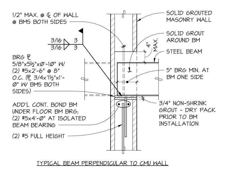
A steel beam frames perpendicularly into a solid grouted masonry wall with a minimum five-inch bearing length on one side. A three-quarter-inch non-shrink grout layer is dry packed prior to beam installation. The bearing plate measures five-eighths by five and one-half inches by ten inches with two number five bars at eight inches on center, or three-fourths by seven and one-half inches by twelve inches when beams occur on both sides. Additional continuous bond beams are provided under the floor beam bearing with two number five bars at four feet zero inches at isolated beam bearing, along with two number five full height solid grout bars around the beam. A half-inch maximum tolerance is maintained at the centerline of the wall for beams on both sides.
3/4 " 3/4" NON-SHRINK GROUT - DRY PACK PRIOR TO BM INSTALLATION 3/16 3 3/16 3 1 /2" 1/2" MAX. @ 7 OF WALL @ BMS BOTH SIDES BRG 5/8"x5½"x0'-10" W/ (2) #5x2'-6" @ 8" O.C. ( 3/4x7½"x1' - 0" W/ BMS BOTH SIDES) ADD'L CONT. BOND BM UNDER FLOOR BM BRG; (2) #5x4'-0" AT ISOLATED BEAM BEARING (2) #5 FULL HEIGHT SOLID GROUT AROUND BM STEEL BEAM 5" BRG MIN. AT BM ONE SIDE 7 1 / 8" TYPICAL BEAM PERPENDICULAR TO CMU WALL MAX. 4" SOLID GROUTED MASONRY WALL
Members view this detail in full resolution, download the CAD files (SVG, PDF), and can adapt it in the built-in CAD editor — export DXF, DWG, or PDF.
Start membership