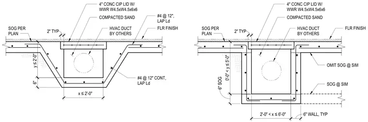
An underground HVAC trench is formed in a slab on grade using cast-in-place concrete with six-inch walls and continuous number four reinforcing bars spaced at twelve inches with required lap lengths. The trench accommodates mechanical ductwork provided by others and is topped with a four-inch cast-in-place concrete lid reinforced with WWR W4.5xW4.5x6x6 welded wire reinforcement over compacted sand. Floor finishes are applied continuously across the top of the assembly as specified per plan.
x ≤ 2'-0" 6" 2" TYP #4 @ 12" CONT, LAP Ld FLR FINISH #4 @ 12", LAP Ld HVAC DUCT BY OTHERS COMPACTED SAND 4" CONC CIP LID W/ WWR W4.5xW4.5x6x6 y ≤ 2'-0" 2'-0" < x ≤ 6'-0" 2" TYP FLR FINISH HVAC DUCT BY OTHERS COMPACTED SAND 4" CONC CIP LID W/ WWR W4.5xW4.5x6x6 6" SOG 6" WALL, TYP 0'-0" < y ≤ 5'-0" OMIT SOG @ SIM SOG @ SIM SOG PER PLAN SOG PER PLAN
Members view this detail in full resolution, download the CAD files (SVG, PDF), and can adapt it in the built-in CAD editor — export DXF, DWG, or PDF.
Start membership