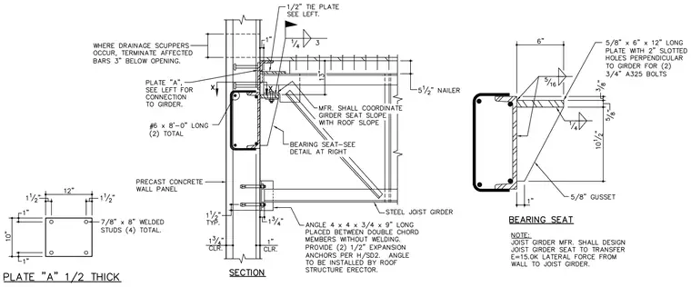
A precast concrete wall panel connects to a steel joist girder using a bearing seat detail with a welded plate assembly and structural steel angles. Plate A, measuring one-half inch thick, embeds in the precast concrete wall panel with four total seven-eighths by eight-inch welded studs. A bearing seat with a five-eighths by six by twelve-inch long plate features two-inch slotted holes perpendicular to the girder for two three-quarter-inch A325 bolts, backed by a five-eighths-inch gusset welded with five-sixteenths and quarter-inch fillet welds. An angle measuring four by four by three-quarters by nine inches long places between double chord members without welding, secured with two half-inch expansion anchors per standard details. A one-half-inch tie plate ties the roof structure to the precast panel, while additional notes require manufacturer coordination for the girder seat slope to match the roof slope and design the seat to transfer a 15.0-kip lateral force from the wall to the joist girder.
Members view this detail in full resolution, download the CAD files (SVG, PDF), and can adapt it in the built-in CAD editor — export DXF, DWG, or PDF.
Start membership