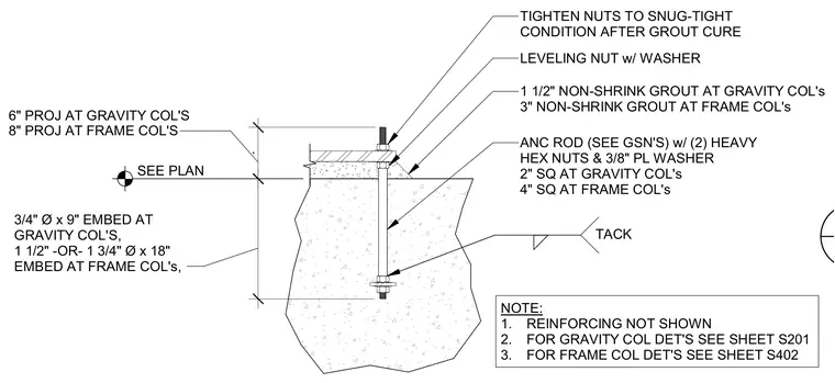
A steel column base plate bears atop a concrete foundation with an intervening layer of non-shrink grout measuring one and one-half inches thick at gravity columns and three inches thick at frame columns. The assembly is secured by anchor rods sized per plan, with three-quarter-inch diameter by nine-inch embedment for gravity columns, and one-and-one-half-inch to one-and-three-quarter-inch diameter by eighteen-inch embedment for frame columns. Each anchor rod features two heavy hex nuts and a three-eighths-inch thick square plate washer measuring two inches square at gravity columns and four inches square at frame columns. A leveling nut with a washer supports the base plate from underneath, while top nuts are tightened to a snug-tight condition after the grout cures. The embedded lower end of the anchor rod is tacked in place. Concrete reinforcement is omitted for clarity.
SEE PLAN . TIGHTEN NUTS TO SNUG-TIGHT CONDITION AFTER GROUT CURE 1 1/2" NON-SHRINK GROUT AT GRAVITY COL's 3" NON-SHRINK GROUT AT FRAME COL's ANC ROD (SEE GSN'S) w/ (2) HEAVY HEX NUTS & 3/8" PL WASHER 2" SQ AT GRAVITY COL's 4" SQ AT FRAME COL's TACK NOTE: 1. REINFORCING NOT SHOWN 2. FOR GRAVITY COL DET'S SEE SHEET S201 3. FOR FRAME COL DET'S SEE SHEET S402 LEVELING NUT w/ WASHER 3/4" Ø x 9" EMBED AT GRAVITY COL'S, 1 1/2" -OR- 1 3/4" Ø x 18" EMBED AT FRAME COL's, 6" PROJ AT GRAVITY COL'S 8" PROJ AT FRAME COL'S
Members view this detail in full resolution, download the CAD files (SVG, PDF), and can adapt it in the built-in CAD editor — export DXF, DWG, or PDF.
Start membership