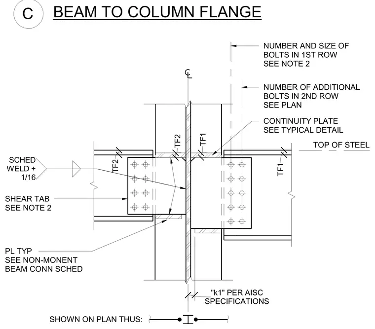
The steel beam connects to the column flange using a welded shear tab with multi-row high-strength bolting sized per plan and schedule. Continuity plates match the beam flange thickness and weld size specifications, aligning with the AISC 'k1' dimension requirements. The shear tab is shop-welded to the column flange and field-bolted to the beam web. Additional non-moment beam connection plates are detailed per structural schedule.
SHEAR TAB SEE NOTE 2 SHOWN ON PLAN THUS: TOP OF STEEL BEAM TO COLUMN FLANGE C SCHED WELD + 1/16 TF2 TF2 TF1 TF1 SPECIFICATIONS "k1" PER AISC NUMBER AND SIZE OF BOLTS IN 1ST ROW SEE NOTE 2 NUMBER OF ADDITIONAL BOLTS IN 2ND ROW SEE PLAN CONTINUITY PLATE SEE TYPICAL DETAIL PL TYP SEE NON-MONENT BEAM CONN SCHED
Members view this detail in full resolution, download the CAD files (SVG, PDF), and can adapt it in the built-in CAD editor — export DXF, DWG, or PDF.
Start membership