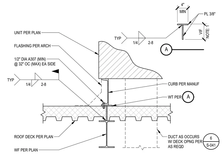
A mechanical rooftop unit bears on a manufacturer-specified curb connected to a structural WT member, which is supported by the roof deck and wide-flange beam per plan. The WT section utilizes a 3/8-inch plate welded with a quarter-inch fillet weld at two inches on center with a four-inch minimum dimension, verified in field. The curb flange is secured to the support assembly using half-inch diameter ASTM A307 minimum anchor bolts spaced at thirty-two inches on center maximum on each side, welded with a quarter-inch fillet weld at two-inch by eight-inch spacing. Architectural flashing interfaces with the unit and curb assembly above the roof deck, while ductwork penetrates the deck opening as required.
DUCT AS OCCURS W/ DECK OPNG PER AS REQD ROOF DECK PER PLAN WF PER PLAN 1/4 2-8 TYP 1/2" DIA A307 (MIN) @ 32" OC (MAX) EA SIDE FLASHING PER ARCH UNIT PER PLAN 6 S-041 WT PER CURB PER MANUF A MIN 4" NOTE: 1 VIF 1/4 2-8 TYP PL 3/8" A
Members view this detail in full resolution, download the CAD files (SVG, PDF), and can adapt it in the built-in CAD editor — export DXF, DWG, or PDF.
Start membership