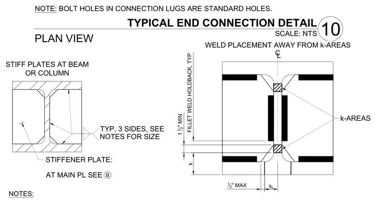
Proper weld placement and stiffener plate configuration at beam or column connections maintain required clearances from the steel k-area. Fillet welds are specified with a one-and-a-half-inch minimum holdback, positioned away from the web-to-flange transition radii. Stiffener plates are welded on three sides with sizes directed per main plate notes. Bolt holes in connection lugs are standard holes.
PLAN VIEW 10 TYPICAL END CONNECTION DETAIL SCALE: NTS NOTE: BOLT HOLES IN CONNECTION LUGS ARE STANDARD HOLES. TYP, 3 SIDES, SEE STIFFENER PLATE: AT MAIN PL SEE B NOTES FOR SIZE NOTES: STIFF PLATES AT BEAM OR COLUMN k 1 1 2 " MIN FILLET WELD HOLDBACK, TYP WELD PLACEMENT AWAY FROM k-AREAS 12 " MAX k-AREAS CL k 1
Members view this detail in full resolution, download the CAD files (SVG, PDF), and can adapt it in the built-in CAD editor — export DXF, DWG, or PDF.
Start membership