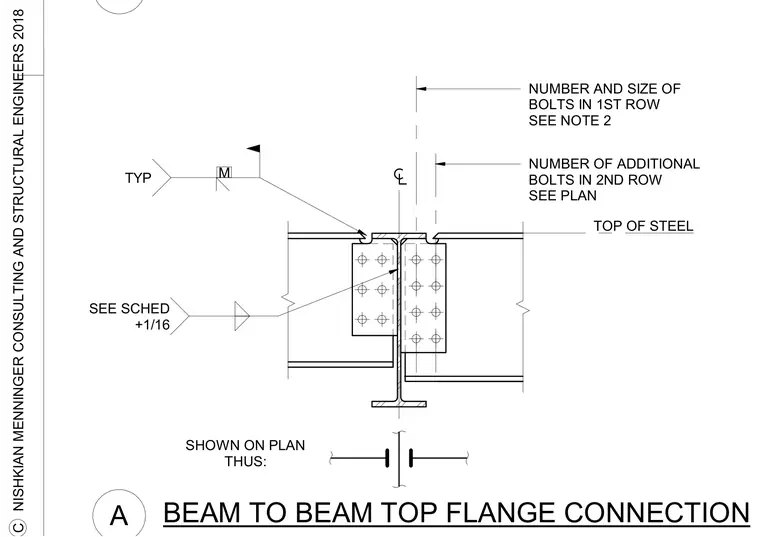
A structural steel beam connects to a supporting beam or collector via a vertical shear tab welded to the support web and bolted to the supported beam web. The top flanges are tied across the joint with a welded plate assembly aligned with a gap dimensioned per plan. Bolt counts and sizes for the primary and secondary rows are sized per schedule and plan notes. Standard field welding and plate clearances are detailed along the top of steel.
TYP M SEE SCHED +1/16 SHOWN ON PLAN THUS: NUMBER AND SIZE OF BOLTS IN 1ST ROW SEE NOTE 2 NUMBER OF ADDITIONAL BOLTS IN 2ND ROW SEE PLAN TOP OF STEEL A BEAM TO BEAM TOP FLANGE CONNECTION B C NISHKIAN MENNINGER CONSULTING AND STRUCTURAL ENGINEERS 2018
Members view this detail in full resolution, download the CAD files (SVG, PDF), and can adapt it in the built-in CAD editor — export DXF, DWG, or PDF.
Start membership